Concrete distributing device and prefabricated part production line

A technology for distributing equipment and concrete, which is applied in the direction of supply equipment, manufacturing tools, ceramic molding workshops, etc., can solve the problems of limited distribution range and insufficient automation, and achieve the effect of high degree of automation, large distribution range, flexible and controllable movement

Inactive Publication Date: 2019-03-22
长沙英平机械制造有限责任公司
View PDF0 Cites 5 Cited by
  • Summary
  • Abstract
  • Description
  • Claims
  • Application Information

AI Technical Summary

Problems solved by technology

[0003] In view of this, the object of the present invention is to provide a concrete distribution device and a precast production line to solve the technical problems of limited distribution range and insufficient automation in the prior art

Method used


Image

  • Concrete distributing device and prefabricated part production line
  • Concrete distributing device and prefabricated part production line
  • Concrete distributing device and prefabricated part production line

Examples


Embodiment 1

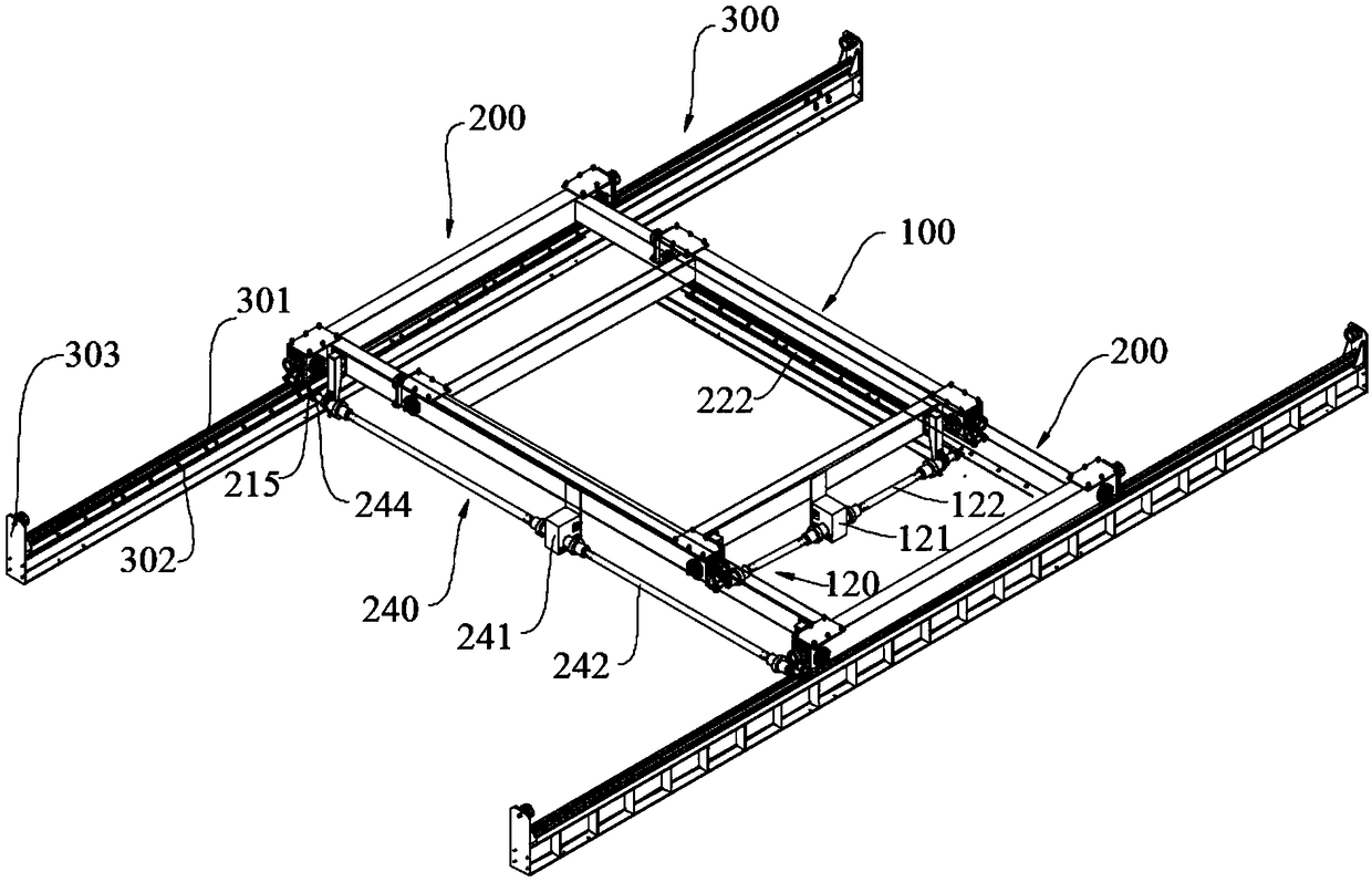
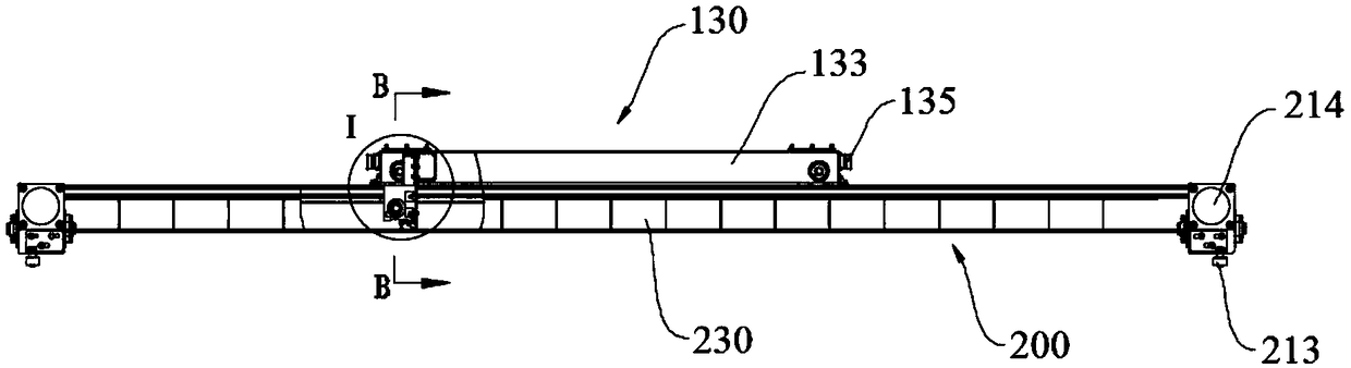
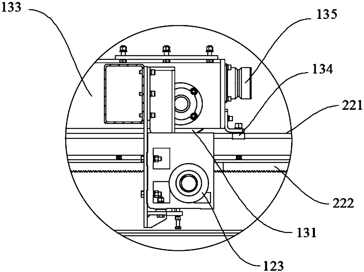
[0029] refer to Figure 1 to Figure 4 , the present embodiment provides a concrete distribution device, the distribution device includes a door frame 300, a cart 200 moving on the door frame 300, a trolley 100 moving on the cart 200, and a distribution mechanism; the distribution mechanism is installed on the trolley 100 . The cart 200 includes two symmetrically arranged first traveling rails 221 and symmetrically arranged two first rack rails 222 , and the first traveling rails 221 are arranged parallel to the first rack rails 222 . The trolley 100 includes two first traveling mechanisms 130 , a first crossbeam 110 and a first transmission mechanism 120 , and two ends of the first crossbeam 110 are vertically connected to corresponding ends of the two first traveling mechanisms 130 . The first transmission mechanism 120 includes a first reducer 121, two first transmission shafts 122 and two first gears 123, one end of each first transmission shaft 122 is connected with the f...

Embodiment 2

[0043] refer to figure 1 , this embodiment provides a concrete distribution device, its structure is basically the same as that of the concrete distribution device in Embodiment 1, the difference is that the cart 200 and the door frame 300 are also driven by rack and pinion track meshing transmission. The second traveling mechanism 210 of the cart 200 moves on the second traveling track 301 of the mast 300 .

[0044] Specifically, the mast 300 includes two symmetrically arranged second running rails 301 and two symmetrically arranged second rack rails 302 , and the second running rails 301 and the second rack rails 302 are arranged in parallel. The cart 200 also includes two second traveling mechanisms 210, a second crossbeam 220, a third crossbeam 230 and a second transmission mechanism 240, and a first traveling rail 221 and a first traveling rail 221 and a The first rack track 222 . Both ends of the second beam 220 are vertically connected to one end of the two second run...

Embodiment 3

[0049]This embodiment provides a prefabricated part production line, and the prefabricated part production line includes the concrete distributing device provided in the above-mentioned embodiments. On the prefabricated parts production line, the transportation device can directly obtain the concrete slurry from the mixing station or the transfer station, transport it to the concrete distribution device through the conveying track, and transfer the concrete slurry to the distribution mechanism. Through the movement of the cart 200 on the door frame 300, the material distribution mechanism is sent to the top of the mold table, and then the trolley 100 moves back and forth on the cart 200 to distribute materials to the mold table.


PUM


Abstract

The invention provides a concrete distributing device and a prefabricated part production line. A large vehicle moves on a portal frame in the concrete distributing device, a small trolley moves on the large trolley, a first transmission mechanism is arranged on the small trolley and drives the first transmission shaft through a first speed reducer, so that first gears at the two ends of the firsttransmission shaft move on first rack rails of the large vehicle; the first transmission shaft is further rotatably connected with a first cross beam in a supported mode, the first cross beam is connected with a first travelling mechanism, and then the first gears are connected with the first rack rails in a meshed transmission mode to drive the first travelling mechanism to move along first travelling rails. The concrete distribution device is flexible and controllable in movement, large in distribution range and high in automation degree.

Description

technical field [0001] The invention relates to the technical field of concrete prefabricated component production equipment, in particular to a concrete distributing device and a prefabricated component production line. Background technique [0002] As the country vigorously promotes urban standard construction, prefabricated buildings are developing rapidly, and the production demand for various prefabricated parts is also increasing. At present, in the production line of related prefabricated components, tow pumps are generally used to pump concrete, and concrete pipelines must be laid on the construction site, which requires a lot of preparation work; the pouring position needs to be manually moved to the outlet of the pipeline, which is inconvenient to use; when the pouring point changes, Some pipelines need to be removed and re-laid, so the production efficiency is low and the labor intensity is high. Therefore, the concrete pouring process mostly adopts crane hoistin...

Claims


Application Information

Patent Timeline
Patent Type & Authority Applications(China)
IPC IPC(8): B28B13/02B28B15/00
CPCB28B13/026B28B15/00
Inventor 刘庆彪朱文波陈德聪
Owner 长沙英平机械制造有限责任公司
Why Eureka
Try Eureka