High-precision camera pan/tilt head
A camera and high-precision technology, which is applied in the direction of machine/stand, supporting machine, mechanical equipment, etc., can solve the problem of low sensitivity, achieve accurate positioning, easy to carry, and good use effect
- Summary
- Abstract
- Description
- Claims
- Application Information
AI Technical Summary
Problems solved by technology
Method used
Image

Examples
Embodiment Construction
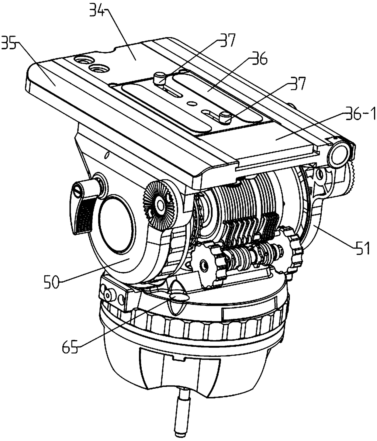
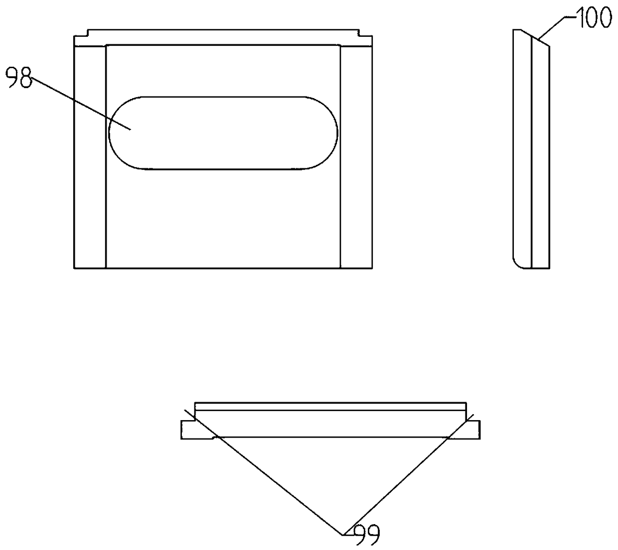
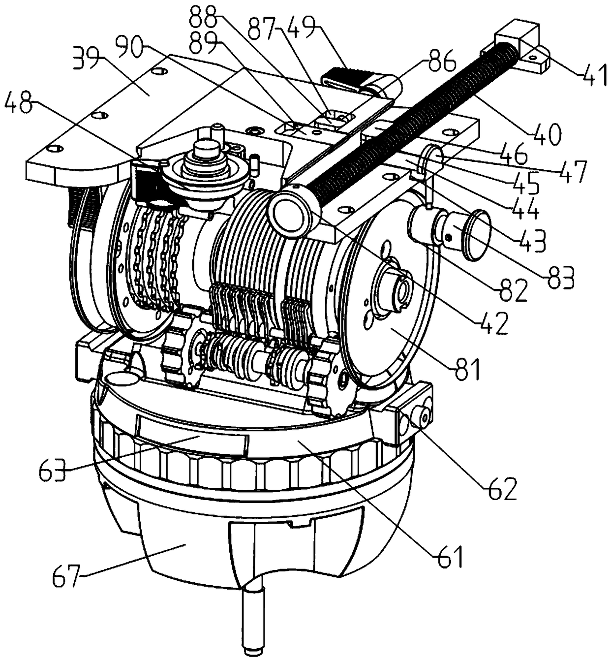
[0072] A high-precision camera platform, including a support slide 34, the support slide 34 includes a slide 35, a baffle 36-1, and a dovetail 39, the slide 35 is slidably mounted on the dovetail 39, and the quick-release plate 36 is fixed on the slide 35 In the middle part, two camera connecting screws 37 are arranged on the quick-release plate 36, and the baffle plate 36-1 is slidably installed on one end of the slide plate 35, and the bottom surface of the baffle plate 36-1 is provided with an eccentric shaft chute 98 which is slidably connected with the eccentric shaft 25, One end of the slide plate 35 is provided with an eccentric rod support threaded hole 96, a baffle plate chute 99, a torsion spring positioning hole 95, and a control post hole 29. The slide plate 35 is provided with a leading screw 40, and one end of the leading screw 40 is provided with a handwheel 42, The other end is provided with lead screw seat 41, and lead screw seat 41 is fixedly connected with sl...
PUM
 Abstract
Description
Claims
Application Information
PatSnap Eureka turns technology decisions into work you can execute. Powered by our Innovation Knowledge Graph, it runs expert workflows across engineering, life sciences, materials and intellectual property. Get your review-ready output in minutes.


