Self-cleaning photovoltaic board for street lamp

A photovoltaic panel and self-cleaning technology, applied in photovoltaic modules, photovoltaic power generation, electric light sources, etc., can solve the problems of affecting the irradiance of components, reduce the photoelectric conversion efficiency, influence, etc., to improve the transparency and irradiance, improve the photoelectricity Conversion efficiency, the effect of eliminating static electricity

Inactive Publication Date: 2019-03-22
张玉梅
View PDF6 Cites 28 Cited by
  • Summary
  • Abstract
  • Description
  • Claims
  • Application Information

AI Technical Summary

Problems solved by technology

In actual use, it is found that during the operation of solar photovoltaic panels, they will be affected by the dust in their environment.
Dust deposition reduces the transparency of the front cover glass, affects the irradiance absorbed by the module, reduces the photoelectric conversion efficiency, and affects the output performance of the module. Therefore, the cleanliness of the surface of the photovoltaic panel is very important

Method used


Image

  • Self-cleaning photovoltaic board for street lamp
  • Self-cleaning photovoltaic board for street lamp
  • Self-cleaning photovoltaic board for street lamp

Examples


Embodiment 1

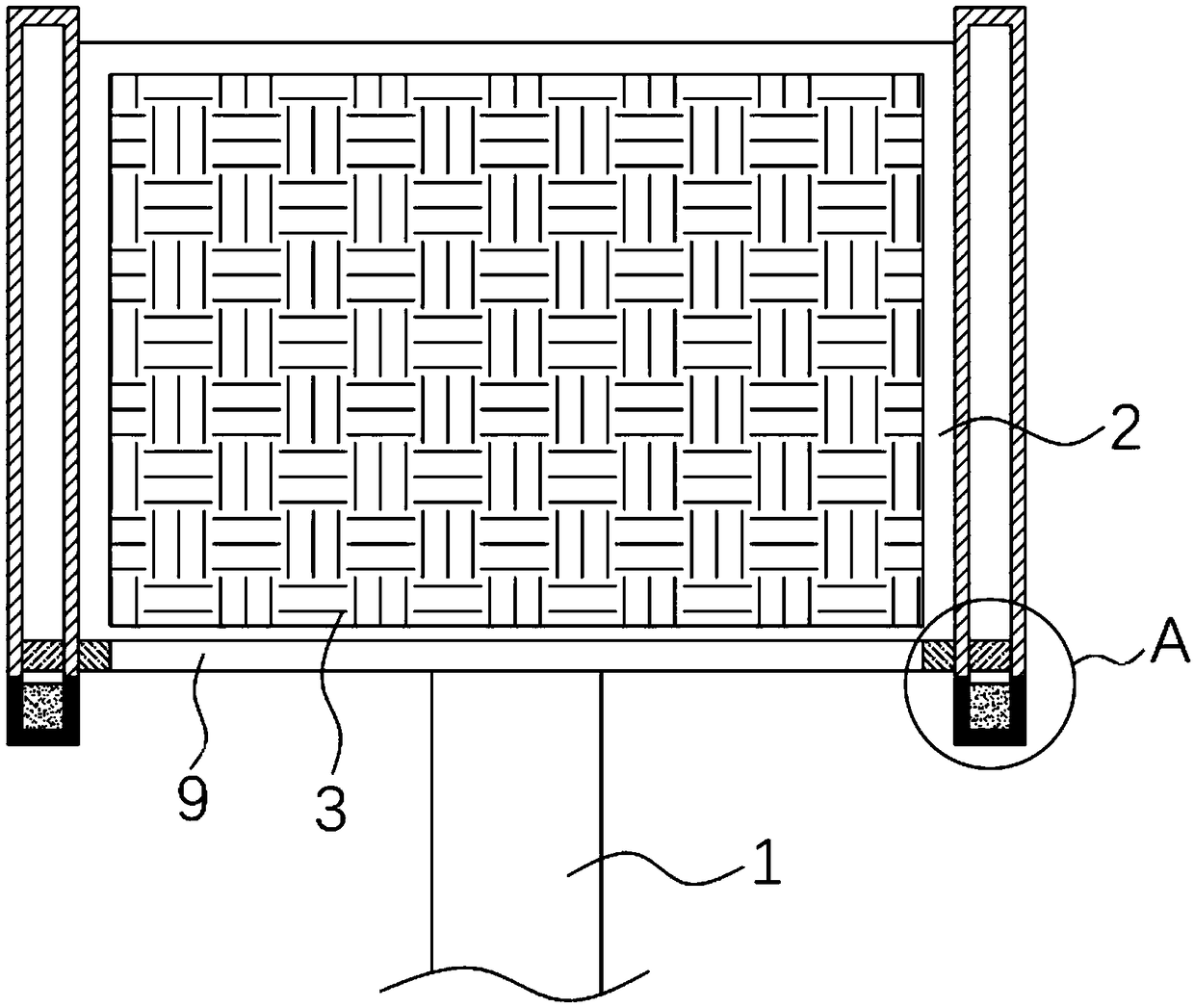
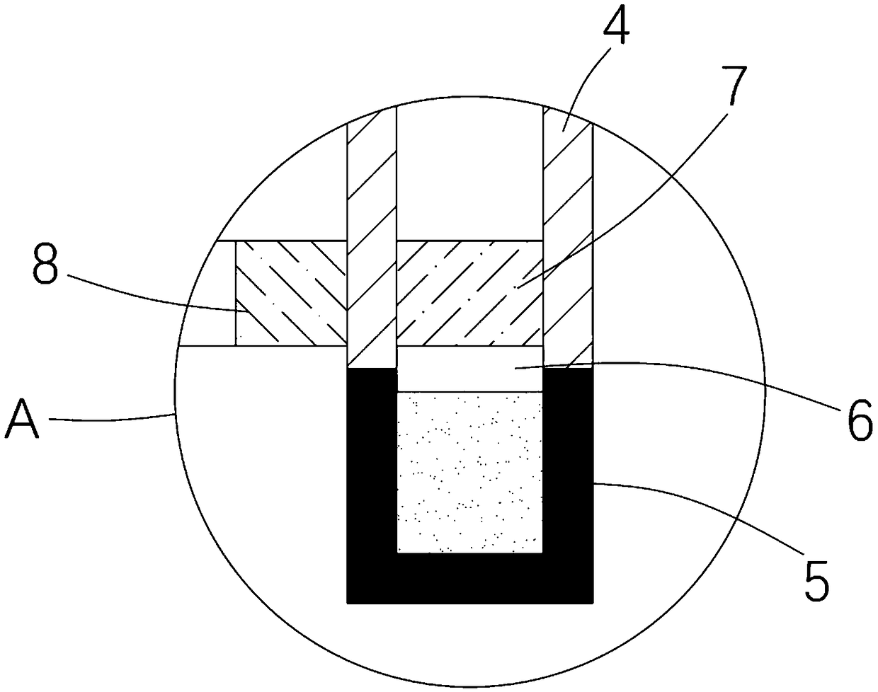
[0019] refer to Figure 1-2 , a self-cleaning photovoltaic panel for street lamps, comprising a light pole 1, a mounting plate 2 and a photovoltaic plate 3, the mounting plate 2 is obliquely installed on the top of the light pole 1, and the photovoltaic plate 3 is fixedly mounted on the upper end surface of the mounting plate 2, The side walls on both sides of the mounting plate 2 are fixedly connected with the moving cylinder 4 with the lower opening, and the lower opening of the moving cylinder 4 is sealed and fixedly connected with the heating cylinder 5, which is made of glass material and its surface is coated with black nickel coating. layer, the black nickel coating has good heat absorption performance, the sum of the width of the moving cylinder 4 and the heating cylinder 5 is greater than the width of the mounting plate 2, and the upper side of the moving cylinder 4 is provided with a first air hole (not shown in the figure), and the moving The cylinder 4 and the heat...

Embodiment 2

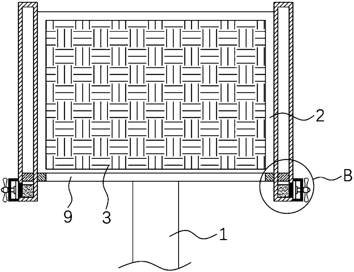
[0023] refer to Figure 3-4 The difference between this embodiment and Embodiment 1 is that: the side walls on both sides of the mounting plate 2 are fixedly connected with elongated tubes 16, the width of the elongated tubes 16 is greater than the width of the mounting plate 2, and the upper sides of the elongated tubes 16 A second air hole (not shown in the figure) is opened on the side, and a gap is provided on the side where the two elongated tubes 16 are far away from each other. One side of the side wall is fixedly connected with a protective box 11 at the corresponding position of the gap, the inner wall of the protective box 11 is fixedly connected with a friction disc 12, the friction disc 12 is connected with the heat conducting plate 10, and the protective box 11 is connected with a ball bearing for rotation. The wind wheel shaft 14, one end of the wind wheel shaft 14 located in the protective box 11 is fixedly connected with the friction block 13 which is in contac...


PUM


Abstract

The invention discloses a self-cleaning photovoltaic board for a street lamp. The self-cleaning photovoltaic board comprises a lamp pole, a mounting board and a photovoltaic board. The mounting boardis obliquely mounted at the top of the lamp pole. The photovoltaic board is fixedly mounted on the upper end face of the mounting board. Motion barrels with openings formed in the lower sides are fixedly connected to the side walls of the two sides of the mounting board. The self-cleaning photovoltaic board has the advantages that heated barrels are utilized for absorbing natural solar energy, thenatural solar energy is converted into heat to be conducted into low-boiling-point evaporated liquor, the low-boiling-point evaporated liquor evaporates to be vaporized and drives two pistons to moveupwards, and driving magnets adsorb driven magnets and drive an electric conduction brush to do sweeping motion upwards; when the temperature is reduced, the low-boiling-point evaporated liquor is liquefied and accumulated in the heated barrels, the two pistons are driven to move downwards, and the driving magnets adsorb the driven magnets and drive the electric conduction brush to do sweeping motion downwards; and destaticizing is carried out on the photovoltaic board, dust is separated from the photovoltaic board under the action of external force, the surface cleanliness of the photovoltaic board is guaranteed, transparency and irradiance are improved, and the photoelectric converting efficiency is improved.

Description

technical field [0001] The invention relates to the technical field of photovoltaic panels, in particular to a self-cleaning photovoltaic panel for street lamps. Background technique [0002] With the deterioration of the environment and the awakening of human awareness of environmental protection, renewable resources such as solar energy and wind energy have been widely used in various fields due to their renewability, environmental protection and energy saving. Among them, road street lamps generally install photovoltaic panels on the top of their support poles to absorb solar energy and convert it into electrical energy for storage, so as to provide sufficient power for street lamp lighting. In actual use, it is found that the solar photovoltaic panel will be affected by the dust in its environment during operation. Dust deposition reduces the transparency of the front cover glass, affects the irradiance absorbed by the module, reduces the photoelectric conversion effici...

Claims


Application Information

Patent Timeline
Patent Type & Authority Applications(China)
IPC IPC(8): F21S9/03F21V33/00H02S40/10F21W131/103
CPCF21S9/035F21V33/00F21W2131/103H02S40/10Y02B20/72Y02E10/50
Inventor 张玉梅
Owner 张玉梅
Why Eureka
Try Eureka