Airplane landing gear loading device and method

A technology of aircraft landing gear and loading device, which is applied to measurement devices, testing of mechanical components, testing of machine/structural components, etc., can solve problems such as failure to achieve the purpose of assessment, data errors, and failure to achieve the most accurate structural assessment. , to achieve the effect of low processing requirements, guaranteed stability and simple operation

Inactive Publication Date: 2019-03-22
CHINA AIRPLANT STRENGTH RES INST
View PDF7 Cites 6 Cited by
  • Summary
  • Abstract
  • Description
  • Claims
  • Application Information

AI Technical Summary

Problems solved by technology

[0002] At present, the crowbar is used in the structural test of the aircraft landing gear. The loading support position of this loading method is fixed, and the loading direction will change during the loading process. This change is determined by the specific structure of the method. The change is Fixed, at this time the loading direction is not consistent with the loading direction of the landing gear assessment, and part of the load is easy to be transmitted along the fixed support point, but cannot be transmitted to the landing gear. This method often does not achieve the most accurate structural assessment. There will be certain errors in the data, and the impact on the landing gear structure with small deformation is not obvious, and the impact on the landing gear with large structural deformation is large, and even the purpose of assessment cannot be achieved.

Method used


Image

  • Airplane landing gear loading device and method
  • Airplane landing gear loading device and method

Examples


Embodiment Construction

[0016] The specific embodiments of the present invention will be described in detail with reference to the summary of the invention and the accompanying drawings.

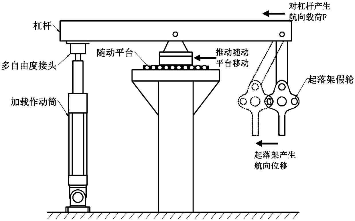
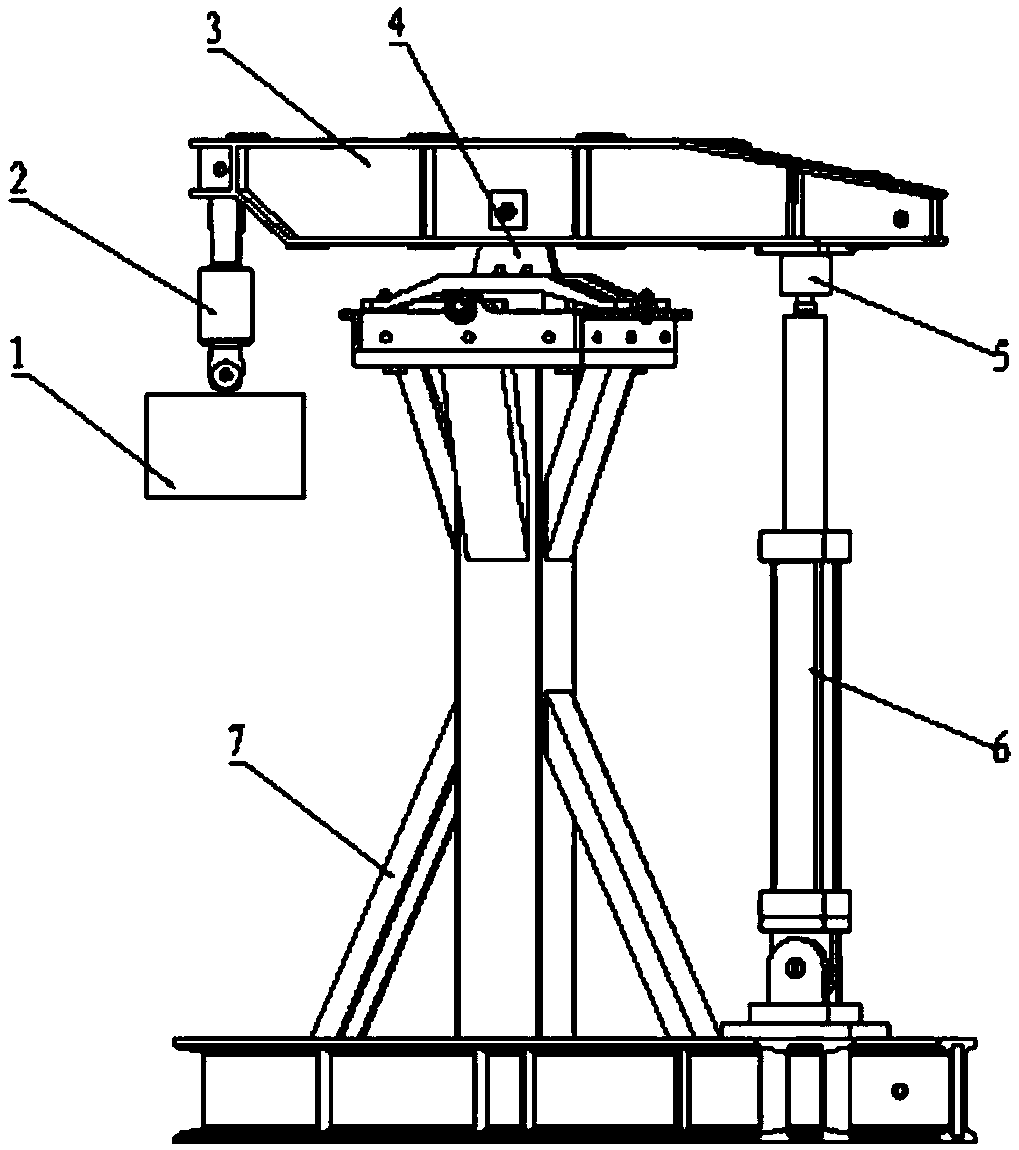
[0017] An aircraft landing gear loading device, comprising a horizontally arranged loading crowbar 3, the loading crowbar 3 transmits the load from one end to the landing gear end, and one end of the loading crowbar 3 is vertically connected with a landing gear dummy wheel 1, the landing gear dummy wheel 1 is the landing gear loading structure. A load cell 2 is connected between the loading crowbar 3 and the landing gear dummy wheel 1, which can control and feedback the load size, and the other end is connected with a hydraulic actuator for loading through a multi-degree-of-freedom joint. The telescopic end of 6, the multi-degree-of-freedom joint can use the universal joint 5. The universal joint 5 is a load transmission device during the loading process to ensure that there will be no jamming during the loading and...


PUM


Abstract

The invention discloses an airplane landing gear loading device. The device comprises a horizontally arranged loading crowbar, wherein one end of the loading crowbar is vertically connected with a landing gear dummy wheel, a force measuring sensor is connected between the loading crowbar and the landing gear dummy wheel, and the other end of the loading crowbar is connected with a hydraulic actuating cylinder through a multi-degree-of-freedom joint; the lower part of the middle of the loading crowbar is hinged to a movable bearing base, and the movable bearing base is placed on a bearing column; the force measuring sensor and the hydraulic actuating cylinder are both electrically connected to a control system. According to a loading process, when a landing gear is loaded in a test, the control system controls load application of the landing gear through the force measuring sensor, the landing gear is deformed in a loading process, the loading crowbar is inclined, the hydraulic actuating cylinder is retracted, the movable bearing base horizontally moves along with the deformation of the landing gear to compensate for a loading end of the landing gear, and the force measuring sensoris inclined because of the loading deformation of the landing gear, so that loading of the landing gear approaches to a loading direction at the examination standard to the maximum degree.

Description

technical field [0001] The invention relates to the field of aircraft structure strength test, in particular to an aircraft landing gear loading device. Background technique [0002] At present, in the structural test of aircraft landing gear, crowbar is used for loading. In this loading method, the loading support position is fixed, and the loading direction will change during the loading process. This change is determined by the specific structural form of this method. The change is Fixed, at this time, the loading direction is inconsistent with the loading direction of the landing gear assessment, and part of the load is easily transmitted along the fixed support points, but cannot be transmitted to the landing gear. This method often fails to achieve the most accurate structural assessment. There will be a certain error in the data obtained, and the impact on the structure of the landing gear with small deformation is not obvious, and the impact on the landing gear with ...

Claims


Application Information

Patent Timeline
Patent Type & Authority Applications(China)
IPC IPC(8): G01M13/00
CPCG01M13/00
Inventor 刘兴科王鑫涛夏龙
Owner CHINA AIRPLANT STRENGTH RES INST
Why Eureka
Try Eureka