A low-cost multi-channel real-time digital instrument panel visual identification method and system

A real-time digital and digital recognition technology, applied in character recognition, character and pattern recognition, instruments, etc., can solve the problems of great difficulty in stable recognition, rising costs, and difficulty in increasing recognition stability

Active Publication Date: 2019-03-22
心鉴智控(深圳)科技有限公司
View PDF6 Cites 3 Cited by
  • Summary
  • Abstract
  • Description
  • Claims
  • Application Information

AI Technical Summary

Problems solved by technology

[0008] 1. Most of the instrument display tasks are displayed in the form of digital diodes. Digital diodes have a fixed refresh rate, which will cause more pictures to show that the diodes that should have been lit should be refreshed when shooting a video continuously. It becomes darker at this frequency, which increases the difficulty of identifying stability;
[0009] 2. The noise of instruments and meters in actual shooting is very large, and the difference between the front and back of each frame of image is very high, such as figure 1 As shown, although the human eye cannot detect it, it is still very difficult for the computer to ensure that the value in the dashboard can be stably recognized in a noisy environment;
[0010] 3. Real-time data update has speed requirements. In the actual production data recording, the frequency of digital changes is relatively fast. How to ensure high-speed and real-time identification of shooting data is still difficult for the current more comprehensive OCR algorithm;
[0011] 4. Resolution requirements under cost constraints, there is a large demand for the monitoring of industrial digital dashboards, but if a high-resolution camera is used, although the accuracy rate can be improved, the speed will decrease and the cost increase will not be acceptable for practical applications. Therefore, how to recognize numbers at low resolution is also an innovation of this algorithm compared with other OCR algorithms;
[0012] 5. In the actual production line, multiple dashboards need to be monitored at the same time, so it is inevitable that most of the dashboards are not completely facing each other in the shooting, and there are various distortions. How to ensure the recognition of the dashboard numbers under various distortions is the task one of the difficulties

Method used


Image

  • A low-cost multi-channel real-time digital instrument panel visual identification method and system
  • A low-cost multi-channel real-time digital instrument panel visual identification method and system
  • A low-cost multi-channel real-time digital instrument panel visual identification method and system

Examples


Embodiment Construction

[0082] It should be noted that the embodiments of the present invention and the features of the embodiments may be combined with each other under the condition of no conflict.

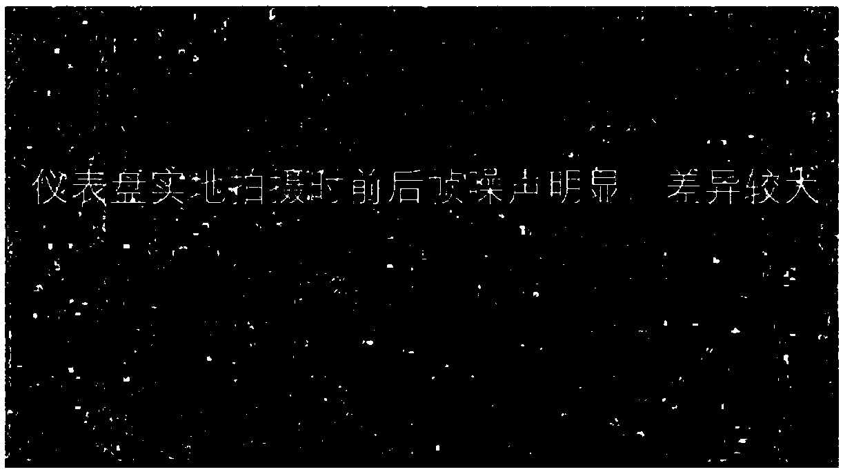
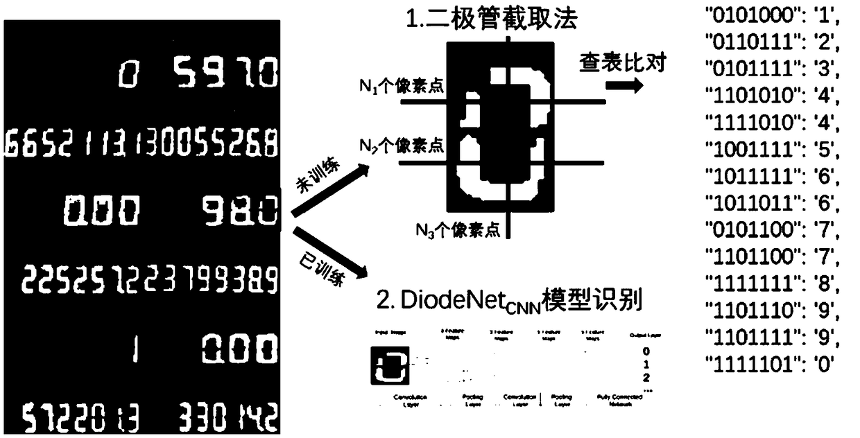
[0083] The present invention proposes a low-cost and multi-channel (simultaneous identification of multiple instrument panels) real-time digital instrument panel identification algorithm: DiodeNet, which solves the identification difficulties of instrument panels one by one, so as to be better applied to industrial production monitoring. Specifically include:

[0084] Step 1. Digital area configuration

[0085] 1.1. Digital tube area configuration: Assuming that there are N digital instrument panels, N is usually greater than 10, the resolution of the camera is W×H, W is usually 1920, H is usually 1080, and the pixels occupied by each instrument panel are W n × H n , n=1, 2,..., N, for each instrument panel, we set 4 points to represent the four corners of the instrument panel reading, P 1n =(w 1n ...


PUM


Abstract

The invention provides a low-cost multi-channel real-time digital instrument panel visual identification method and system. Includes digital tube area configuration and digital tube decimal point information configuration S2: performing sub-area ROI preprocessing; S3:performing Sub-region identification; S4: performing Sub-region post-processing; 5, train, updating and teste that digital recognition model; S6: Publishing completion model. The invention solves the identification difficulties of the instrument panel one by one so as to be better applied to industrial production monitoring.

Description

technical field [0001] The invention belongs to the field of industrial production monitoring, and in particular relates to a low-cost multi-channel real-time digital instrument panel visual recognition method and system. Background technique [0002] The task of identifying various instrument representations is different from the traditional optical character recognition (OCR) problem, and is closer to the text recognition problem of natural scenes. The research in this area can be divided into detection and recognition as a whole. Different from the OCR problem of documents, the detection of numbers in various instrument representations is a very difficult thing itself, and many scholars have made a lot of attempts. [0003] Before the emergence of deep learning methods, methods based on traditional handcraft features, including connected regions and HOG-based detection frame descriptions, were more mainstream; Regions) to obtain character candidates, and regard these cha...

Claims


Application Information

Patent Timeline
Patent Type & Authority Applications(China)
IPC IPC(8): G06K9/32G06K9/62G06K9/34
CPCG06V30/153G06V10/25G06V2201/02G06V30/10G06F18/214
Inventor 罗晓忠毛子靖蒋晟龙林清华
Owner 心鉴智控(深圳)科技有限公司
Why Eureka
Try Eureka