
Feeding inlet guiding device and anti-static belt conveyor

A technology of belt conveyor and material guide device, applied in the direction of conveyor, conveyor objects, static electricity, etc., can solve the problems of difficult shell disassembly, waste of material transportation, long distance of belt conveyor, etc., and achieve non-static blanking operation , The overall structure design is reasonable, reducing the effect of relative movement

Pending Publication Date: 2019-03-26
ZHENGZHOU JINGU GRAIN MECHANICAL ENG EQUIP
View PDF15 Cites 2 Cited by
  • Summary
  • Abstract
  • Description
  • Claims
  • Application Information

AI Technical Summary

Problems solved by technology

When the material is unloaded from the head and enters the next process, due to the effect of static electricity, part of the material in contact with the belt will adhere to the belt and cannot enter the next process. After the material adheres to the belt, it will move circularly with the belt. During the circular movement, when the adhered material reaches a certain amount, due to the vibration of the belt during operation, a part of the adhered material falls into the belt conveyor shell along the length of the belt, and with the long-term operation of the belt conveyor, , the material in the shell of the belt conveyor will accumulate more and more, which will eventually affect the normal operation of the belt conveyor, and the distance of the belt conveyor is long, and the shell is difficult to disassemble, resulting in troublesome cleaning
On the other hand, it also causes waste in the process of material transportation

Method used


Image

  • Feeding inlet guiding device and anti-static belt conveyor
  • Feeding inlet guiding device and anti-static belt conveyor
  • Feeding inlet guiding device and anti-static belt conveyor

Examples


Embodiment Construction

[0033] In order to make the purpose, technical features and technical effects of the technical solution of the present invention more clear, the exemplary solutions of the embodiments of the present invention will be clearly and completely described below in conjunction with the drawings of specific embodiments of the present invention.

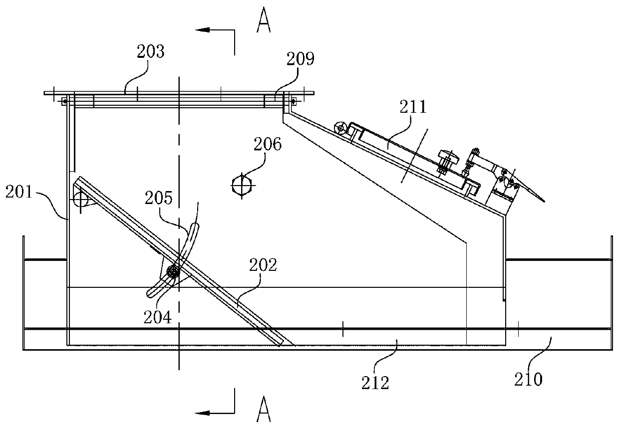
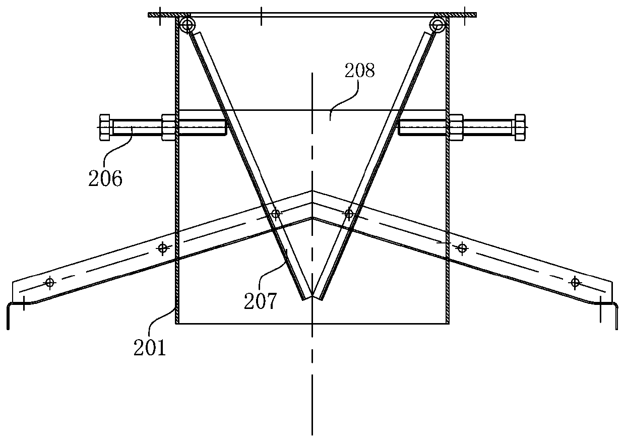
[0034] see figure 1 with figure 2 , a material inlet guide device 200 of the present invention is used for feeding belt conveyors, including a hopper housing 201, a blanking bottom plate 202 and a first adjustment assembly, and the top of the hopper housing 201 is provided with a material inlet 203 , the bottom of the hopper shell 201 is open, and a hopper cover 210 is provided; the blanking bottom plate 202 is pivotally arranged on the inner side wall of the hopper shell 201, and on the blanking bottom plate 202 A discharge opening 212 is formed between the bottom of the hopper housing 201; the first adjustment component drives the dischar...


PUM


Abstract

The invention belongs to the technical field of bulk material conveying, and provides a feeding inlet guiding device. The feeding inlet guiding device is used for feeding of the belt conveyor, and comprises a feeding hopper shell, a falling bottom plate and a first adjusting assembly, a feeding inlet is formed in the top of the feeding hopper shell, and an opening is formed in the bottom of the feeding hopper shell; the falling bottom plate is pivotally arranged on the inner side wall of the feeding hopper shell, and a falling port is formed between the falling bottom plate and the bottom of the feeding hopper shell; and the first adjusting assembly drives the falling bottom plate to swing,and adjusts the included angle between the falling direction and the belt conveyor. The invention further discloses an anti-static belt conveyor. According to the feeding inlet guiding device and the anti-static belt conveyor, overall structural design is reasonable, through design of a feeding hopper, the speed and angle of a bulk material entering the air cushion conveyor belt can be effectively controlled, relative motion between the bulk material and the air cushion conveyor belt is reduced to the maximum extent, thus static electricity is prevented from producing between the bulk material and the conveyor belt, and then the problem of adhesion of the material at the discharging end is avoided.

Description

technical field [0001] The invention belongs to the technical field of bulk material conveying, and in particular relates to a material guide device at a material inlet and an antistatic belt conveyor. Background technique [0002] In ports, wharves, for bulk material (wheat, corn, soybean) transportation, belt conveyors are mainly used to transport materials. By moving the grab bucket, the bulk material is grabbed from the cabin and put into the hopper. The bulk material flows from the hopper to the conveyor belt of the belt conveyor through the chute, and is transported to the next process along with the belt. [0003] But because the belt of the belt conveyor runs at a certain speed, when the material falls from the chute to the belt, the initial velocity of the material is inconsistent with the belt speed of the belt conveyor, resulting in a speed difference between the material and the belt when it reaches the belt, and the gap between the material and the belt Frictio...

Claims


Application Information

Patent Timeline
Patent Type & Authority Applications(China)
IPC IPC(8): B65G47/18B65G23/22B65G15/60H05F3/00
CPCH05F3/00B65G15/60B65G23/22B65G47/18B65G2201/0202
Inventor 陈锡建成宇刘晓东姜永顺贾垚郭建勋
Owner ZHENGZHOU JINGU GRAIN MECHANICAL ENG EQUIP
Learn More