Scribing apparatus

A scribing and equipment technology, applied in glass manufacturing equipment, glass cutting devices, glass production, etc., can solve problems such as the inability to cut and bond substrates smoothly, and achieve the effect of accurate modification and easy cutting

Pending Publication Date: 2019-03-26
TOP ENG CO LTD
View PDF2 Cites 0 Cited by
  • Summary
  • Abstract
  • Description
  • Claims
  • Application Information

AI Technical Summary

Problems solved by technology

However, there is a problem that the material of the black matrix and the adhesion between the paste and the black matrix cannot be cut and bonded smoothly.

Method used


Image

  • Scribing apparatus
  • Scribing apparatus
  • Scribing apparatus

Examples


no. 1 example

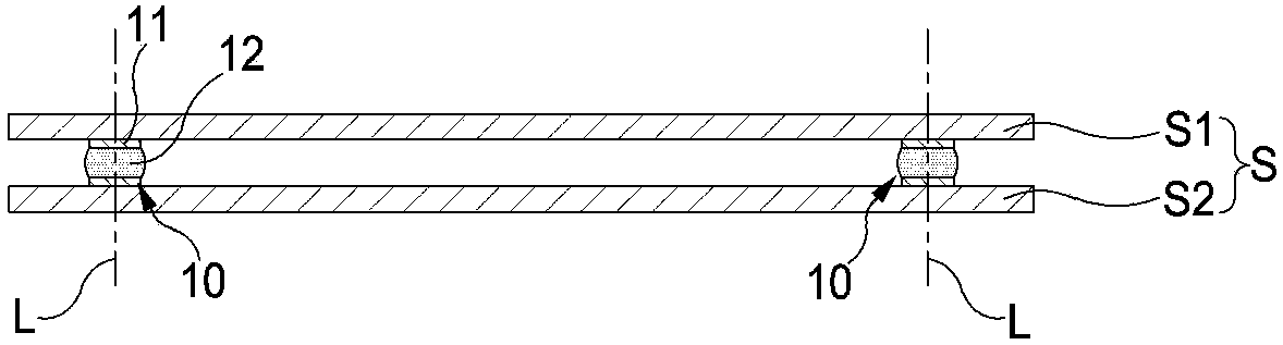
[0086] As in the first embodiment of the present invention, when there are multiple media 10 between the bonded substrates S, the first laser beam irradiation head 410 and the second laser beam irradiation head 420 move in the direction of the Z axis, and can sequentially irradiate A type of laser beam for a medium 11 and a second medium 12 .

[0087] The scribing apparatus in the first embodiment of the present invention irradiates a plurality of kinds of media 10 with laser beams respectively corresponding to kinds of a plurality of kinds of media 10 arranged in a predetermined pattern between bonded substrates S, so that at least a part of the media 10 is modified. , forming scribe lines on the bonded substrate S along the pattern of the medium 10 to cut the bonded substrate S. Thereby, it becomes easy to cut the bonded board|substrate S together with the medium 10 provided between the bonded board|substrates S. As shown in FIG.

[0088] Below, refer to Figure 10 , to de...


PUM


Abstract

The present invention relates to a dicing apparatus for cutting a bonded substrate along a pattern of a medium, the bonded substrate including a plurality of patterns arranged in a predetermined pattern between the first substrate, the second substrate, the second substrate, and the second substrate The medium, comprising: a dicing unit that forms a scribe line along a pattern of the medium on a surface of the bonded substrate; and a laser beam irradiation unit that illuminates at least a portion of the medium The laser beam causes at least partial modification of the medium, and the laser beam irradiation unit respectively irradiates the plurality of mediums with laser beams of a corresponding kind thereof.

Description

technical field [0001] The present invention relates to a scribing device for forming a scribing line on a substrate for cutting the substrate. Background technique [0002] Generally, liquid crystal display panels, organic electroluminescent display panels, inorganic electroluminescent display panels, transmissive projection substrates, reflective projection substrates, etc. used for flat panel The mother glass panel is obtained by cutting to a predetermined size. [0003] The mother glass panel is a bonded substrate formed by bonding the first substrate and the second substrate. The first substrate can include thin film transistors, and the second substrate can include color filters. The first substrate and the second substrate are bonded together using paste as an adhesive. There is liquid crystal and / or electronic components between the first substrate and the second substrate. [0004] The process of cutting the bonded substrate into unit substrates includes a scrib...

Claims


Application Information

Patent Timeline
IPC IPC(8): C03B33/023C03B33/10
CPCC03B33/023C03B33/10C03B33/033C03B33/102C03B33/105C03B33/037Y02P40/57
Inventor 金镇洛
Owner TOP ENG CO LTD
Why Eureka
Try Eureka