Telescopic overhung support and mounting method thereof

A cantilever and oblique support technology, applied in pillars, erection/assembly of bridges, processing of building materials, etc., can solve the problems of high scaffolding cost, high height, and troublesome construction of supporting formwork, so as to achieve low construction cost and reduce construction cost. , the effect of improving efficiency

Pending Publication Date: 2019-03-26
ZHEJIANG INST OF COMM
View PDF0 Cites 10 Cited by
  • Summary
  • Abstract
  • Description
  • Claims
  • Application Information

AI Technical Summary

Problems solved by technology

When the top floor of a single-story building needs to be a concrete cantilevered platform, the construction of the supporting formwork below is very troublesome, and the supporting formwork at the lower part of the steel-concrete composite beam bridge is also very troublesome. Scaffolding still needs more construction period
If permanent support is added to the structure, it will increase the cost and the self-weight of the structure

Method used


Image

  • Telescopic overhung support and mounting method thereof
  • Telescopic overhung support and mounting method thereof
  • Telescopic overhung support and mounting method thereof

Examples


Embodiment 1

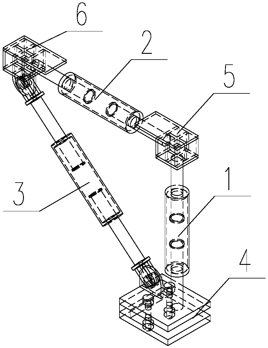
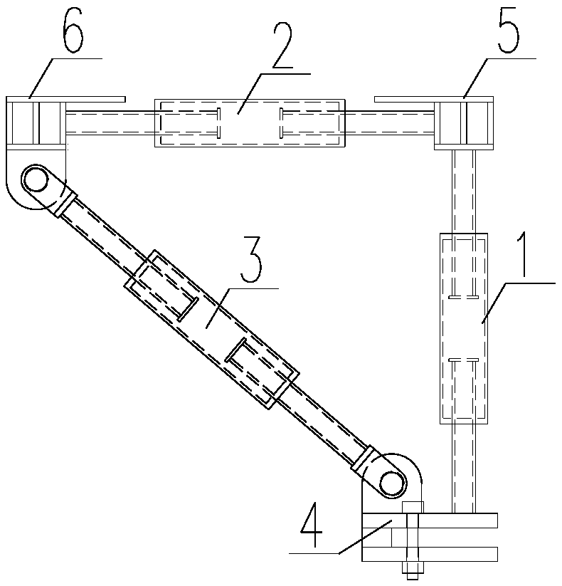
[0036] Embodiment 1: as Figure 1-8 As shown, a telescopic cantilever support includes a vertical support 1, a horizontal support 2, an oblique support 3, a lower support 4, an upper support 5 and a cantilever support 6;

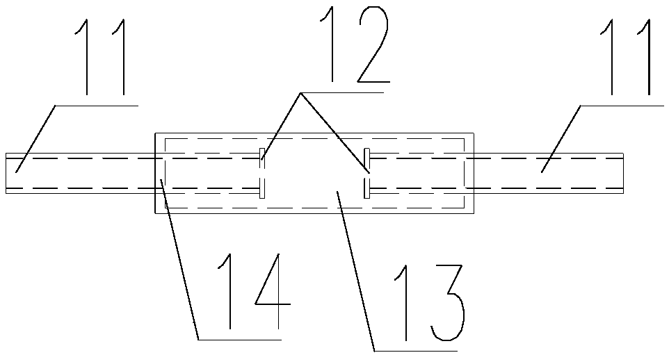
[0037] The vertical support includes a screw 11, a screw end plate 12, a sleeve 13 and a sleeve end plate 14 containing internal threads, wherein the two screw rods have opposite thread directions. In and out at the same time, the screw end plate can prevent the screw from falling off;

[0038] The horizontal support 2 includes a screw 21, a screw end plate 22, a sleeve 23 and a sleeve end plate 24 containing internal threads, wherein the two screw rods have opposite thread directions. In and out at the same time, the screw end plate can prevent the screw from falling off;

[0039] The oblique support 3 consists of seven parts: screw rod 31, screw end plate 32, sleeve 33, sleeve end plate 34 with internal thread, connecting plate 35, connecting lug plate 3...

Embodiment 2

[0044] Embodiment 2: This embodiment also includes a method for installing a telescopic cantilevered support, including the following steps:

[0045] Step 1: According to the height of the steel beam 8 (see Figure 10 ) or steel box girder 7 (see Figure 9 ) height and cantilever distance to choose the appropriate cantilever support;

[0046] Step 2: Set the distance between cantilevered supports after calculation and analysis;

[0047] Step 3: Adjust the overhang value of the overhang support according to the distance of the overhang plate, and fix the overhang distance on the ground;

[0048] Step 4: Set up a simple scaffold or use a climbing car to install a cantilever support;

[0049] Step 5: install formwork 9 or reinforced truss floor deck 9 on the upper surface of support upper support 5 and cantilever support 6 (see Figure 9 , 10 );

[0050] Step 6: After the concrete pouring is completed, remove the support.


PUM


Abstract

The invention discloses a telescopic overhung support and a mounting method thereof. The telescopic overhung support comprises six parts, namely a vertical support, a horizontal support, an inclined support, a lower bracket, an upper bracket and an overhung bracket; the lower bracket and the upper bracket are tightly pressed in an upper flange and a lower flange by the vertical support, and then the lower bracket is clamped, so that the self-stability of the support is ensured. The distance between the horizontal support and the inclined support is adjusted to meet the overhung requirement, aformwork is installed or steel bar truss floor support plates are laid, and then concrete is poured. The structure has the advantages that the construction cost is low and the usage amount of scaffolds is reduced through the telescopic overhung support; meanwhile, the telescopic overhung support can be repeatedly used, and the construction cost is reduced; the construction efficiency is high, thetime of erecting scaffolds is saved, and the formwork installation efficiency is improved; construction is convenient: the overhung support is convenient to mount and dismount, and can be directly mounted and dismounted by a ladder truck.

Description

technical field [0001] The patent of the invention belongs to the field of bridges and steel structure buildings, and specifically relates to a scalable cantilever support and its installation method, which can be used for temporary support when the concrete slab is poured on the cantilever part of the steel-concrete composite girder bridge deck, and can also be used Temporary support for high-altitude cantilevered slabs in steel structures. Background technique [0002] With the development of society, there are more and more buildings with high single-storey heights, and the application of steel structures in bridges is becoming more and more extensive. When the top floor of a single-story building needs to be a concrete cantilevered platform, the construction of the supporting formwork below is very troublesome, and the supporting formwork at the lower part of the steel-concrete composite beam bridge is also very troublesome. Scaffolding also takes more time. If permane...

Claims


Application Information

Patent Timeline
Patent Type & Authority Applications(China)
IPC IPC(8): E01D21/00E04G25/04E04G21/00
CPCE01D21/00E04G21/00E04G25/04
Inventor 赵伟
Owner ZHEJIANG INST OF COMM
Why Eureka
Try Eureka