
Textile dryer

A technology of a dryer and a drying box, applied in the textile field, can solve the problems of shortening the service life of heating components, affecting the drying efficiency of cloth, reducing the energy efficiency of the dryer, etc., and achieving the effect of being convenient for recycling and reuse.

Inactive Publication Date: 2019-03-26
汪正娟
View PDF0 Cites 2 Cited by
  • Summary
  • Abstract
  • Description
  • Claims
  • Application Information

AI Technical Summary

Problems solved by technology

Although this method improves the thermal efficiency, the tail gas also contains a certain amount of water vapor. If this part of water vapor is not removed, it will affect the drying efficiency of the cloth.
[0005] 3. In the current conventional dryer, the setting of the air inlet of the hot air device and the heating part is unreasonable. When the outside air enters the box, it cannot fully contact the heating part, resulting in the inability to efficiently transfer the heat on the heating part. Into the hot air, on the one hand, it shortens the service life of the heating component itself, and on the other hand, it also reduces the energy efficiency of the dryer.

Method used


Image

  • Textile dryer
  • Textile dryer
  • Textile dryer

Examples


Embodiment Construction

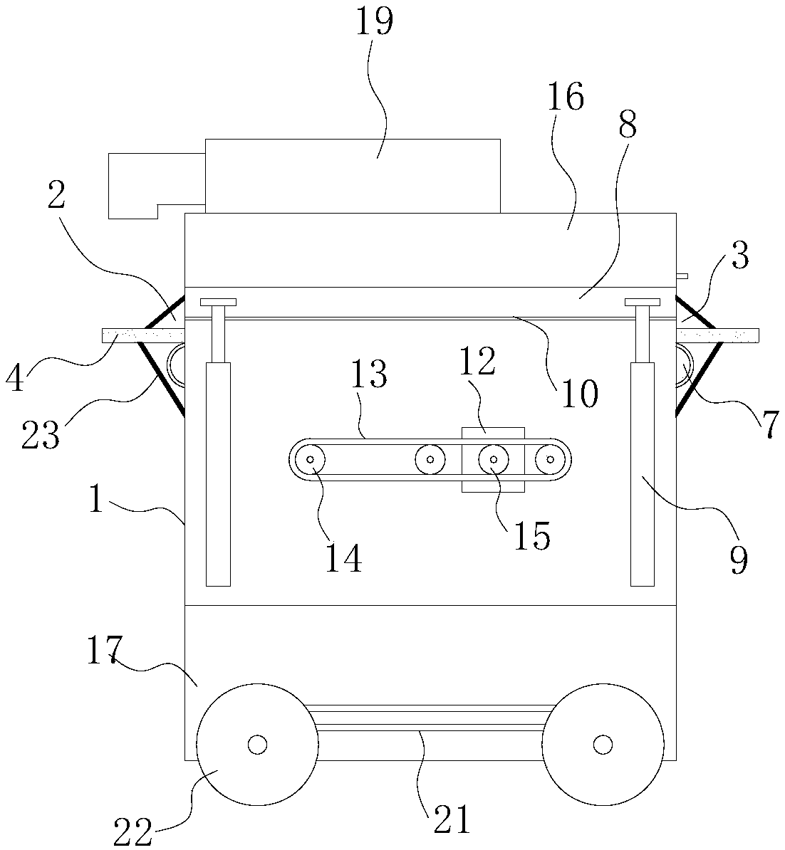
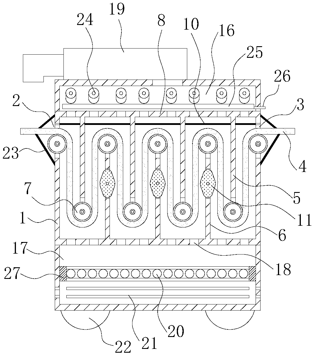
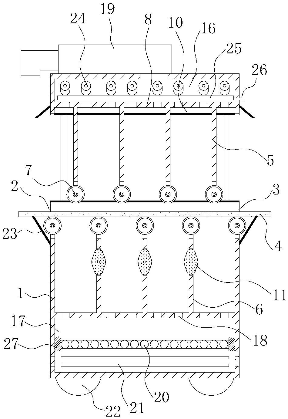
[0025] Such as Figure 1-5 A textile dryer shown includes a drying box 1 and a hot air device. The left side of the drying box 1 is provided with a cloth inlet 2, and the right side is provided with a cloth outlet 3, and the cloth inlet 2 and the cloth outlet 3 are used for cloth 4 to enter and exit the drying box 1, so the cloth inlet 2 and the outlet The length of cloth mouth 3 should be suitable with the width of cloth 4. The hot air device is used to send hot air for heating the cloth 4 into the drying box 1, and the cloth 4 is dried by the hot air while passing through the drying box 1 through the cloth inlet 2 and the cloth outlet 3. That is to say, the function of the hot air device is to generate hot air, and make the hot air flow in the drying box 1 to heat and dry the cloth 4 .

[0026] Compared with the traditional dryer, one of the main differences of the present invention is: as Figure 4 As shown, multiple vertical upper partitions 5 and lower partitions 6 are...


PUM


Abstract

The invention relates to the technical field of textile, and aims to provide a textile dryer capable of dehumidifying and reusing exhaust gas. According to the technical scheme, the textile dryer comprises a drying box and a hot air device, a fan is arranged at the top of a negative pressure chamber, and an inlet of the fan communicates with an air outlet of the negative pressure chamber; an electric heating component is arranged in an air inlet chamber, and an air inlet is formed in the side wall of the air inlet chamber; an outlet of the fan faces cloth at a cloth feeding opening, a dehumidifying component is arranged in the negative pressure chamber, the dehumidifying component includes a plurality of dehumidifying rods arranged side by side along the front-rear direction of the negative pressure chamber, and the two ends of each dehumidifying rod are connected with the front side face and the rear side face of the negative pressure chamber; and each dehumidifying rod is composed ofa core rod and a hygroscopic sponge arranged outside the core rod in a sleeving manner. The textile dryer can effectively remove moisture in the hot air exhaust gas, and therefore the waste heat in the exhaust gas are conveniently recycled and reused.

Description

technical field [0001] The invention relates to the technical field of textiles, in particular to a textile dryer. Background technique [0002] As we all know, the dryer is an important equipment widely used in the textile field, and its performance directly affects the quality of the produced cloth. Existing conventional dryers generally include a box, in which a hot air device is installed, and the cloth passes through the box during the drying process, and the hot air device blows out hot air to dry the cloth. However, the inventor found after long-term research that, The existing textile dryer also has the following defects. [0003] 1. The current dryers basically use hot air for drying, and their drying efficiency mainly depends on the heat exchange rate between the hot air and the moisture in the cloth, the length of the heat exchange stroke, etc. However, in order to damage the cloth due to the high temperature of the textile, the control of the heat exchange rate...

Claims


Application Information

Patent Timeline
IPC IPC(8): F26B13/08F26B21/00F26B23/00F26B25/00F26B25/04F26B25/12
CPCF26B13/08F26B21/001F26B23/002F26B25/00F26B25/005F26B25/04F26B25/12Y02P70/10
Inventor 汪正娟
Owner 汪正娟
Learn More