Metal material heat shrinkage parameter measuring device used for 3D printing and analogue simulation

A metal material, 3D printing technology, applied in the field of 3D printing, can solve the problems of single measurement function, low measurement accuracy, deformation and cracking of 3D printing parts, etc., to achieve the effect of flexible operation, large reference value and high accuracy

Inactive Publication Date: 2019-03-26
广西慧思通科技有限公司
11 Cites 0 Cited by

AI-Extracted Technical Summary

Problems solved by technology

[0002] 3D printing is a kind of rapid prototyping technology. It is a technology based on digital model files, using powdered metal or plastic and other bondable materials to construct objects by layer-by-layer printing. Technical issues, during the 3D printing process, the metal material melts rapidly, and the volume change due to its inherent thermal exp...

Method used

In the present invention, need to open heating element 12 before device work, inner cylinder 10 is carried out preheating, once the metal material of melting encounters ice-cold cylinder wall to cool down rapidly, affects the accuracy of shrinkage parameter measurement, simultaneously Remove the air in the chamber at the lower end of the piston 13 in the inner cylinder 10 in advance, and then use the negative pressure to inhale the molten metal material. As the volume of the liquid gradually increases, the piston 13 moves upward, and the liquid level of the collected liquid rises gradually, adding to a suitable level. Once the volume is reached, the initial scale of the collected liquid can be estimated. At the same time, the water level sen...

Abstract

The invention relates to a metal material heat shrinkage parameter measuring device used for 3D printing and analogue simulation. The device comprises a heat shrinkage generation assembly, a heat shrinkage parameter collecting assembly, a controller, connection pipes, a water pump, a liquid storage box, horizontal measurement equipment and a base; the heat shrinkage generation assembly comprises an outer cylinder, an inner cylinder, a heating part, a piston, a feeding/discharging pipe, a water outlet pipe and a water inlet pipe; the heat shrinkage generation assembly is installed on the base;the heat shrinkage parameter collecting assembly is arranged at the upper end of the heat shrinkage generation assembly; the controller, the water pump and the liquid storage box which are arranged onthe periphery of the heat shrinkage generation assembly are arranged on the base; the water pump, the liquid storage box and the heat shrinkage generation assembly are connected through the connection pipes. The device is flexible to operate, by means of alternate action of cooling liquid and the heating part, effects of heating and cooling conditions on the volume of a metal material can be simulated respectively, and meanwhile, the alternate action of the cooling liquid and the heating part is in cooperation with temperature monitoring, so that obtained data is large in reference value andhigh in accuracy.

Application Domain

Technology Topic

Image

  • Metal material heat shrinkage parameter measuring device used for 3D printing and analogue simulation
  • Metal material heat shrinkage parameter measuring device used for 3D printing and analogue simulation
  • Metal material heat shrinkage parameter measuring device used for 3D printing and analogue simulation

Examples

  • Experimental program(1)

Example Embodiment

[0022] In order to make the objectives, technical solutions and advantages of the present invention clearer, the present invention will be further described in detail below with reference to the specific embodiments and the accompanying drawings. It should be understood that these descriptions are exemplary only and are not intended to limit the scope of the invention. Also, in the following description, descriptions of well-known structures and techniques are omitted to avoid unnecessarily obscuring the concepts of the present invention.
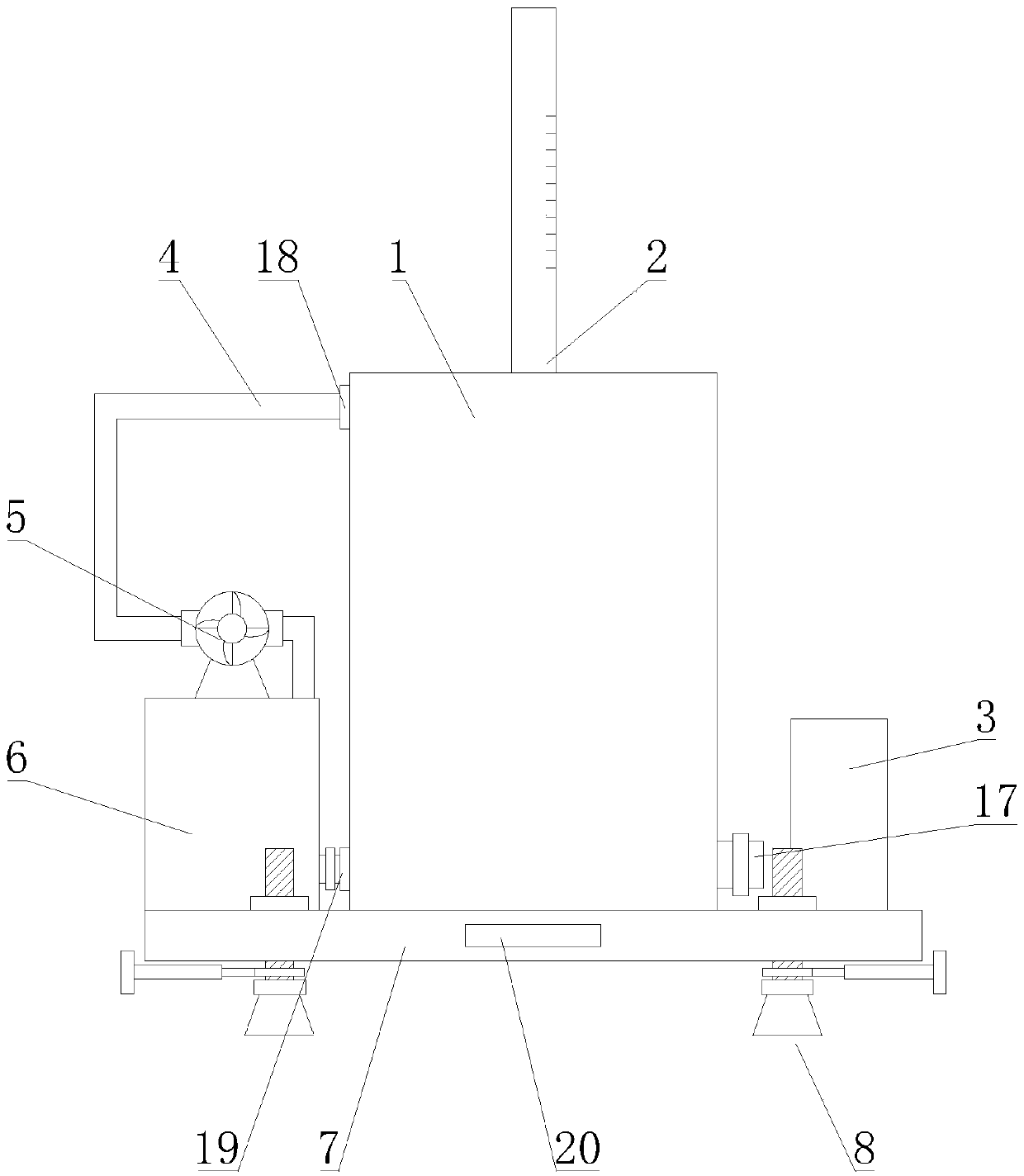
[0023] figure 1 It is a schematic structural diagram of a metal material heat shrinkage parameter measurement device for 3D printing simulation proposed by the present invention.
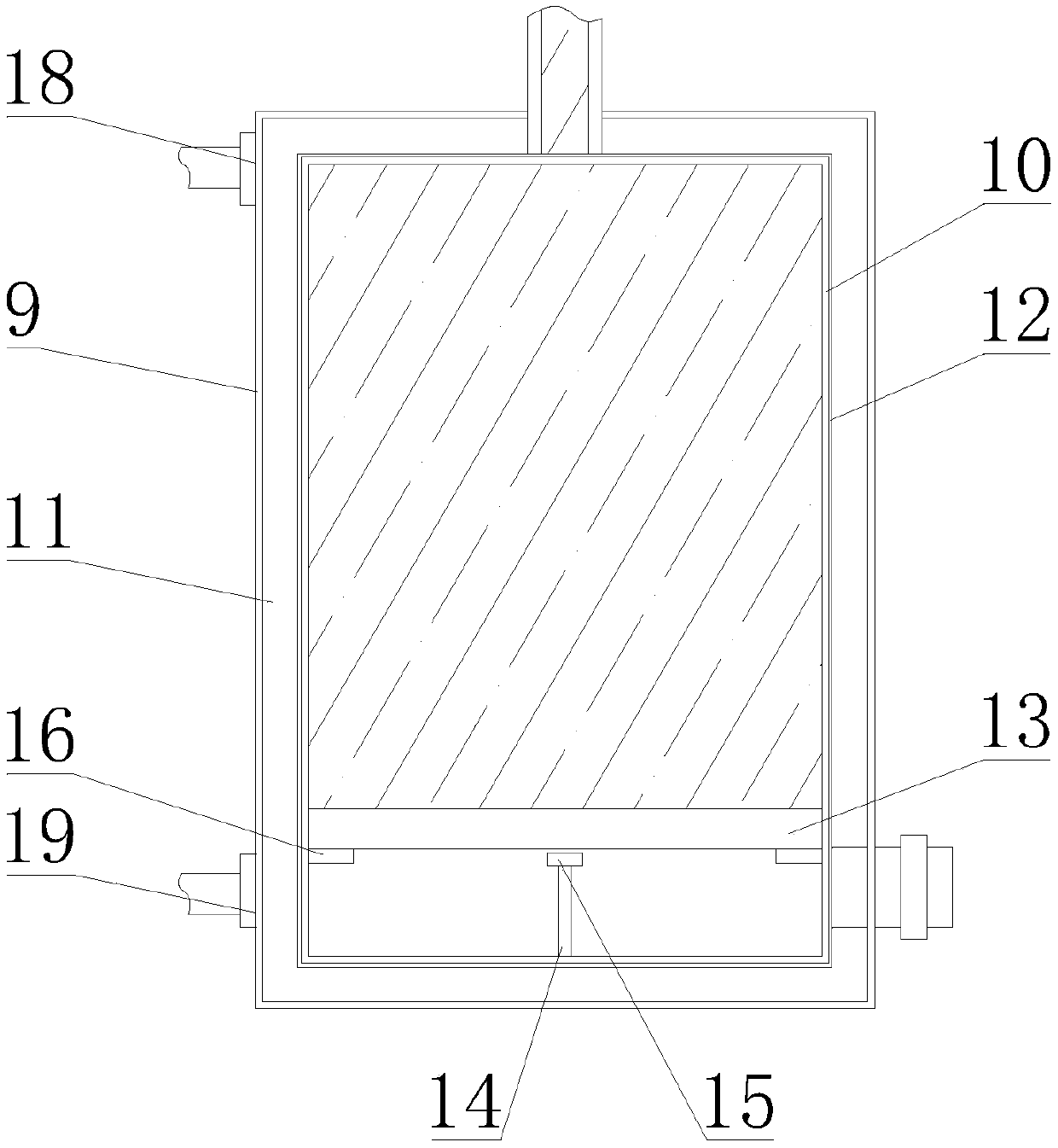
[0024] figure 2 It is a structural schematic diagram of the heat shrinkage generating component in a metal material heat shrinkage parameter measurement device for 3D printing simulation proposed by the present invention.
[0025] like Figure 1-2 As shown, a metal material heat shrinkage parameter measurement device for 3D printing simulation is characterized in that it includes a heat shrinkage generating component 1, a heat shrinkage parameter collection component 2, a controller 3, a connecting pipe 4, a water pump 5, and a liquid storage tank 6. Level measuring device 20 and base 7; thermal shrinkage generating assembly 1 includes outer cylinder 9, inner cylinder 10, heating element 12, piston 13, inlet/outlet pipe 17, outlet pipe 18 and water inlet pipe 19; outer cylinder The body 9 is arranged on the base 7; the inner cylinder 10 is arranged inside the outer cylinder 9, and a cooling chamber 11 is arranged between the two; the cooling chamber 11 is filled with cooling liquid; the heating element 12 is arranged on the inner cylinder 10 close to the outer cylinder One end of the body 9; the piston 13 is slidably connected to the inner wall of the inner cylinder 10 in the vertical direction, and a sealing structure is formed between the two; the chamber at the upper end of the piston 13 is equipped with a collection liquid; and communicate with the chamber at the lower end of the piston 13; the outlet pipe 18 and the water inlet pipe 19 are respectively arranged at the upper end and the lower end of the outer cylinder 9, and both communicate with the cooling chamber 11; the heat shrinkage parameter collection assembly 2 includes an observation sleeve and a water level Induction device; the upper and lower ends of the observation sleeve are open, and the observation sleeve is vertically arranged on the top of the heat shrinkage assembly 1, and communicated with the chamber at the upper end of the piston 13; the water level sensing device is arranged inside the observation sleeve; the liquid storage The tank 6 is arranged on the base 7; the water pump 5 is arranged on the liquid storage tank 6; the connecting pipe 4 is arranged in multiple groups; the water pump 5, the liquid storage tank 6, the outlet pipe 18 and the water inlet pipe 19 are respectively connected by the connecting pipe 4; The controller 3 is arranged on the base 7, and the controller 3 is provided with a single-chip microcomputer, and the controller 3 communicates with the water level sensing device;
[0026] In an optional embodiment, the bottom of the inner cylinder 10 is provided with a connecting rod 14 ; the top of the connecting rod 14 is provided with a temperature sensing device 15 ; the temperature sensing device 15 is communicatively connected with the controller 3 .
[0027] In an optional embodiment, a limiting member 16 is provided on the inner wall of the inner cylinder 10 corresponding to the movement track of the piston 13 .
[0028] In an optional embodiment, the connecting sleeve is made of a transparent material, and a scale is provided on the outer wall; a color-developing component is added to the collected liquid.
[0029] In the present invention, the heating element 12 needs to be turned on before the device works to preheat the inner cylinder 10, so as to avoid the rapid cooling of the molten metal material when it encounters the cold cylinder wall, which will affect the accuracy of the measurement of the shrinkage parameter, and at the same time remove it in advance The air in the chamber at the lower end of the piston 13 in the inner cylinder 10 is then sucked into the molten metal material by negative pressure. As the volume of the liquid gradually increases, the piston 13 moves up, and the liquid level of the collected liquid rises gradually. After adding to a suitable volume, The initial scale of the collected liquid can be estimated, and at the same time, the water level sensing device accurately records the position of the collected liquid, and then the cooling liquid and the heating element 12 are used to cool and heat the metal material, and the temperature sensing device 15 extends into the metal material. Record the temperature change, the water level sensing device records the change of the collected liquid volume at the same time, and finally the controller 3 collects the data and processes it to obtain the thermal shrinkage parameter of the metal material. The effects of heating and cooling conditions on the volume of metal materials are simulated separately, and at the same time combined with temperature monitoring, the obtained data has great reference value and high accuracy.
[0030] image 3 It is a structural schematic diagram of the installation components in a metal material thermal shrinkage parameter measurement device for 3D printing simulation proposed by the present invention.
[0031] like image 3 As shown, the base 7 is provided with an installation assembly 8; the installation assembly 8 includes a support rod 22, a fixing member 23, a level adjustment member 24, a telescopic member 25 and an installation member 26; the support rod 22 is provided with external threads; the base 7 is provided with There is a first threaded hole matched with the support rod 22; the support rod 22 is arranged in the vertical direction, and is threadedly connected to the base 7; The threaded hole is threadedly connected to the support rod 22, and is located at the upper end of the base 7; the horizontal adjustment member 24 is located at the lower end of the support rod 22; Mount 26.
[0032] In an optional embodiment, mounting holes are provided on the mounting member 26 .
[0033] In an optional embodiment, the horizontal adjustment member 24 includes an adjustment member 27 and a support member 21; the adjustment member 27 is a ring structure, and the inner wall of the ring is provided with internal threads that match the support rod 22; the support member 21 is the upper and lower ends An open trumpet-shaped structure, the upper end of the support member 21 is connected with the adjustment member 27 .
[0034] It should be noted that when installing the device, install the support rod 22 on the base 7, adjust the length of the lower end of the support rod 22 to ensure that the height of the device is appropriate, then tighten the fixing part 23, fix the support rod 22, and then adjust the telescopic part The length of 25, and the fixed installation of the device is realized by the cooperation of the mounting part 26 and the fixing nail. The installation and disassembly operations are simple and flexible. Therefore, by rotating the support rod 22 and the adjusting member 27, the level of the device is adjusted to ensure the accuracy of the measurement results.
[0035] It should be understood that the above-mentioned specific embodiments of the present invention are only used to illustrate or explain the principle of the present invention, but not to limit the present invention. Therefore, any modifications, equivalent replacements, improvements, etc. made without departing from the spirit and scope of the present invention should be included within the protection scope of the present invention. Furthermore, the appended claims of this invention are intended to cover all changes and modifications that fall within the scope and boundaries of the appended claims, or the equivalents of such scope and boundaries.

PUM

no PUM

Description & Claims & Application Information

We can also present the details of the Description, Claims and Application information to help users get a comprehensive understanding of the technical details of the patent, such as background art, summary of invention, brief description of drawings, description of embodiments, and other original content. On the other hand, users can also determine the specific scope of protection of the technology through the list of claims; as well as understand the changes in the life cycle of the technology with the presentation of the patent timeline. Login to view more.

Similar technology patents

Multi-bent-portion device and industrial endoscope

PendingCN106444005AFlexible operationStrong portabilityTelescopesBone shapeLiquid-crystal display
Owner:西安众筹梦康电子科技有限公司

Preparation method of Stefan parchment paper

InactiveCN101768896AFlexible operationStable production processVegetable/imitation parchmentEnergy consumptionRaw material
Owner:MCC MEILI CLOUD COMPUTING IND INVESTMENT CO LTD

Socket, adaptor, and assembly jig

Owner:PANASONIC INTELLECTUAL PROPERTY MANAGEMENT CO LTD

Classification and recommendation of technical efficacy words

  • Flexible operation
  • High reference value
Why Eureka
Try Eureka