A fatigue deformation evolution model of concrete based on Weibull equation

A fatigue deformation and evolution model technology, applied in CAD numerical modeling, instruments, data processing applications, etc., can solve the problems of difficulty in popularization and application, complex model forms, etc., and achieve the effect of simplifying detection equipment, reducing calculation amount, and being easy to use

Active Publication Date: 2019-03-26
ZHEJIANG UNIV
View PDF4 Cites 0 Cited by
  • Summary
  • Abstract
  • Description
  • Claims
  • Application Information

AI Technical Summary

Problems solved by technology

Existing models usually require multiple parameters including fatigue strain, fatigue stress, elastic modulus, and material fitting parameters. The model form is relatively complex, and generally requires iterative calculations, so it is difficult to popularize and apply it in engineering construction.

Method used


Image

  • A fatigue deformation evolution model of concrete based on Weibull equation
  • A fatigue deformation evolution model of concrete based on Weibull equation
  • A fatigue deformation evolution model of concrete based on Weibull equation

Examples


Embodiment 1

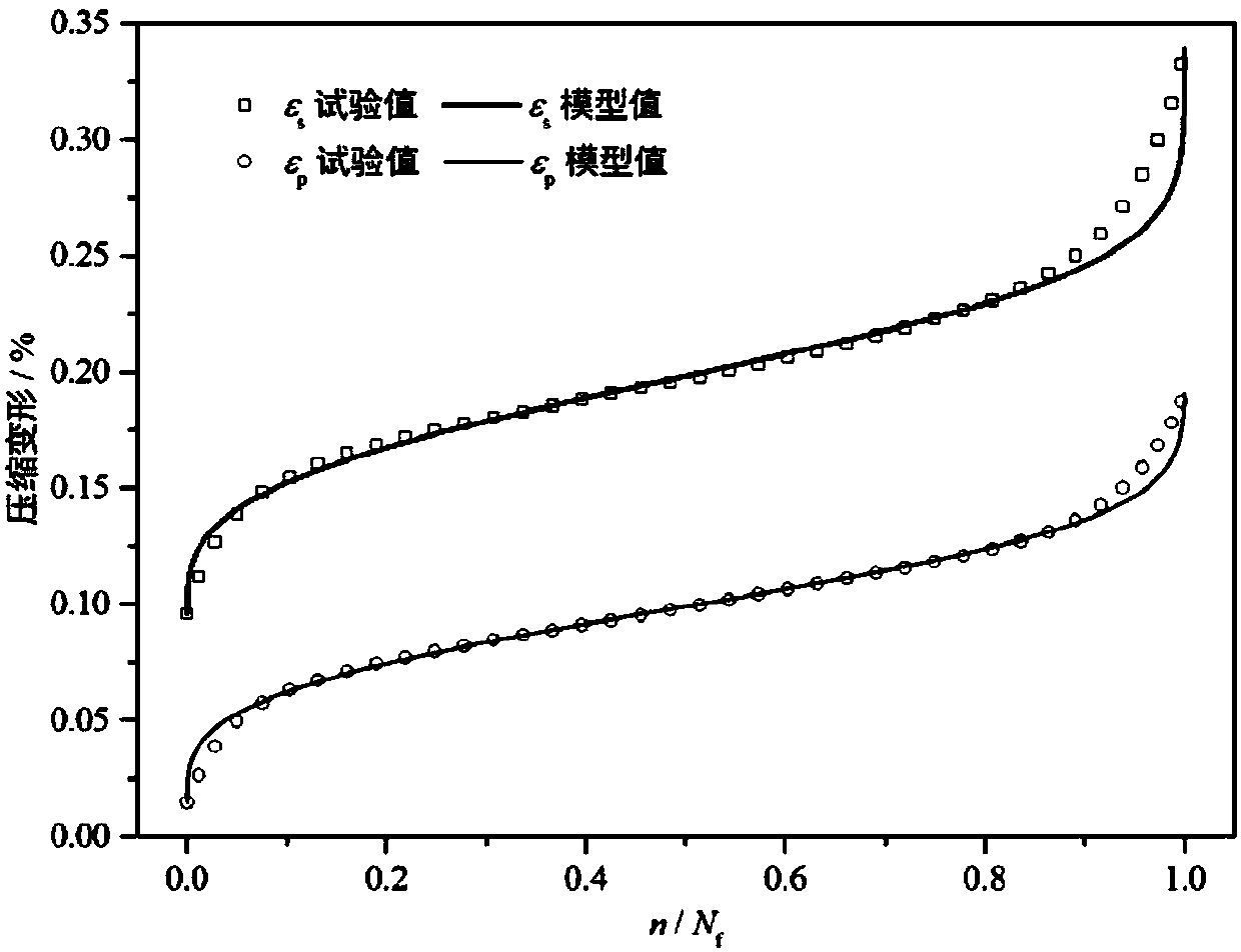
[0023] This embodiment adopts the fatigue of the concrete compression fatigue sample D22 in "Fig.11" in the document "Holmen J O. Fatigue of concrete by constant and variable amplitude loading [J]. ACI Special Publication, 1982, 75:71-110." deformation result. The maximum deformation ε of the sample under compressive fatigue load s , Residual deformation ε p The evolution law of figure 1 shown. It should be noted that the maximum deformation ε of the fatigue specimen s Obtained directly from said literature, the residual deformation ε p Calculated from fatigue deformation results in the literature.

[0024] according to figure 1 The maximum deformation ε shown s The experimental value of , through fitting, the location parameter ε can be obtained s0 =0.09582, scale parameter λ s = 0.11497, shape parameter k s = 3.16309. Thus, the following fatigue deformation evolution model can be obtained:

[0025] n / N f =1-exp(-((ε s -0.09582) / 0.11497) 3.16309 ),(r 2 =0.9971...

Embodiment 2

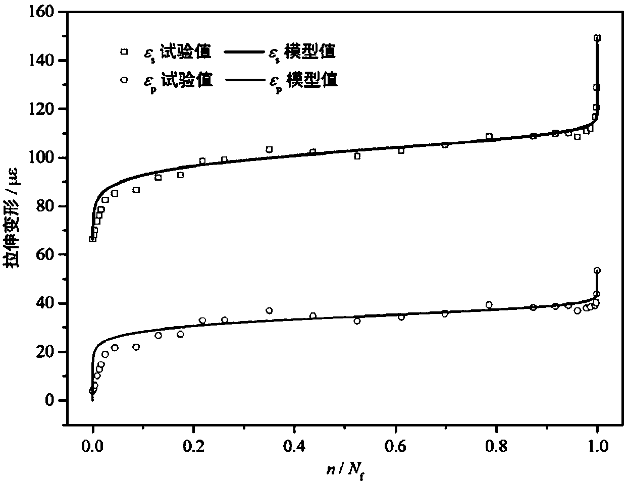
[0030] This embodiment adopts the document "Chen X, Bu J, Fan X, et al. Effect of loading frequency and stress level on low cycle fatigue behavior of plain concrete in direct tension [J]. Construction and Building Materials, 2017, 133: 367-375 The fatigue deformation results of the concrete tensile fatigue specimen S=0.85test data in "Fig.8c" in ". The maximum deformation ε of the sample under the action of tensile fatigue load s , Residual deformation ε p The evolution law of figure 2 shown. It should be noted that the maximum deformation ε of the fatigue specimen s and residual deformation ε p were obtained directly from the literature.

[0031] according to figure 2 The maximum deformation ε shown s The experimental value of , through fitting, the location parameter ε can be obtained s0 = 38.21874, scale parameter λs = 66.41625, shape parameter k s = 11.44255. Thus, the following fatigue deformation evolution model can be obtained:

[0032] n / N f =1-exp(-((ε ...

Embodiment 3

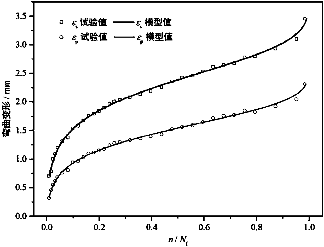
[0037] This embodiment adopts the literature "Liu W, Xu S, Li H.Flexural fatigue damage model of ultra-high toughness cementitious composites on base of continuum damagemechanics[J].International Journal of Damage Mechanics,2014,23(7):949-963 . "The fatigue deformation results of the fiber concrete bending fatigue specimen S0.80 in "Fig.3a". The maximum deformation ε of the sample under bending fatigue load s , Residual deformation ε p The evolution law of image 3 shown. It should be noted that the maximum deformation ε of the fatigue specimen s Obtained directly from said literature, the residual deformation ε p Calculated from fatigue deformation results in the literature.

[0038] according to image 3 The maximum deformation ε shown s The experimental value of , through fitting, the location parameter ε can be obtained s0 =-2.27807, scale parameter λ s = 4.85335, shape parameter k s =9.28728. Thus, the following fatigue deformation evolution model can be obtain...


PUM


Abstract

The invention discloses a concrete fatigue deformation evolution model based on Weibull equation. In the developing field of modern civil engineering, the fatigue behavior of concrete has become one of the focuses of attention. How to accurately characterize the fatigue evolution of concrete and predict the fatigue life of concrete has become an important issue in the field of engineering construction. The model provided by the invention can be used for characterizing the deformation evolution law of concrete under compression, tensile and flexural fatigue loads. It has many advantages such asapplicable load forms, concise expression, easy to use and high precision. The calculation amount can be greatly reduced in use, and only two fatigue parameters, the number of fatigue load cycles n and the deformation Epsilon corresponding to a certain stress in the nth cycle, can be measured, which simplifies the testing equipment. The model can provide important technical support for the wholeprocess of engineering design, construction, testing and maintenance.

Description

technical field [0001] The invention belongs to the technical field of concrete fatigue deformation evolution model. Background technique [0002] Since the advent of Portland cement in the 19th century, concrete has been widely used in transportation, construction, water conservancy, marine and other engineering fields, and is the most used material in engineering construction. At the beginning of the 20th century, with the construction and development of reinforced concrete bridges, related research on the fatigue performance of concrete materials was gradually carried out. Since the 21st century, with the construction of large-scale infrastructure such as highways, high-speed railways, super high-rise buildings, super-high dams, sea-crossing bridges, and ocean platforms, concrete structures are facing more complex and harsh conditions such as cyclic loads and alternating environments. Conditions of service. On the other hand, the further development of concrete structur...

Claims


Application Information

Patent Timeline
Patent Type & Authority Applications(China)
IPC IPC(8): G06F17/50
CPCG06F30/367G01N33/383G01N2203/0005G01N2203/0073G01N2203/0218G06Q50/08G06F2111/10G06F2119/04G01B21/32G01N3/565G06F17/18G06F30/00
Inventor 李庆华黄博滔徐世烺
Owner ZHEJIANG UNIV
Why Eureka
Try Eureka