Aiming method of a bar code reader and a aiming device thereof

A barcode reader and aiming device technology, which is applied to instruments, electromagnetic radiation induction, induction recording carriers, etc., can solve the problems of reducing production efficiency, unable to clearly indicate the scanning range of the code, and the user's failure to scan the code, etc. Scan code success rate, expand the scope of application, and optimize the effect of user experience

Inactive Publication Date: 2019-03-26
SHENZHEN IDATA TECH CO LTD
View PDF4 Cites 2 Cited by
  • Summary
  • Abstract
  • Description
  • Claims
  • Application Information

AI Technical Summary

Problems solved by technology

The one-shaped positioning pattern is only suitable for the reading and positioning of the one-dimensional code; the cross-shaped positioning pattern is more suitable for the reading and positioning of the two-dimensional code. People manufacture special-shaped lenses based on the principle of light diffraction (or refraction) To produce a cross-shaped positioning pattern, this kind of special-shaped lens is large in size, which is not conducive to the miniaturization of components, and the assembly repeatability of the special-shaped lens is very poor, requiring manual repeated debugging, which reduces production efficiency
More importantly, the existing positioning patterns such as a line and a cross are only roughly positioned when scanning the code, and cannot clearly indicate the scanning range, which may cause the user to fail to scan the code, and need to be adjusted repeatedly to scan the code. Affects efficiency; if a larger positioning pattern is to be formed to clearly indicate the scanning range, the positioning pattern formed by the traditional LED light source is not clear, but after switching to a laser light source with concentrated energy, the laser passes through the positioning formed by the traditional special-shaped lens The pattern is so small that it is impossible to clearly indicate the scanning range at all

Method used


Image

  • Aiming method of a bar code reader and a aiming device thereof
  • Aiming method of a bar code reader and a aiming device thereof
  • Aiming method of a bar code reader and a aiming device thereof

Examples


Embodiment Construction

[0033] In order to facilitate a better understanding of the purpose, structure, features, and effects of the present invention, the present invention will now be further described in conjunction with the accompanying drawings and specific embodiments.

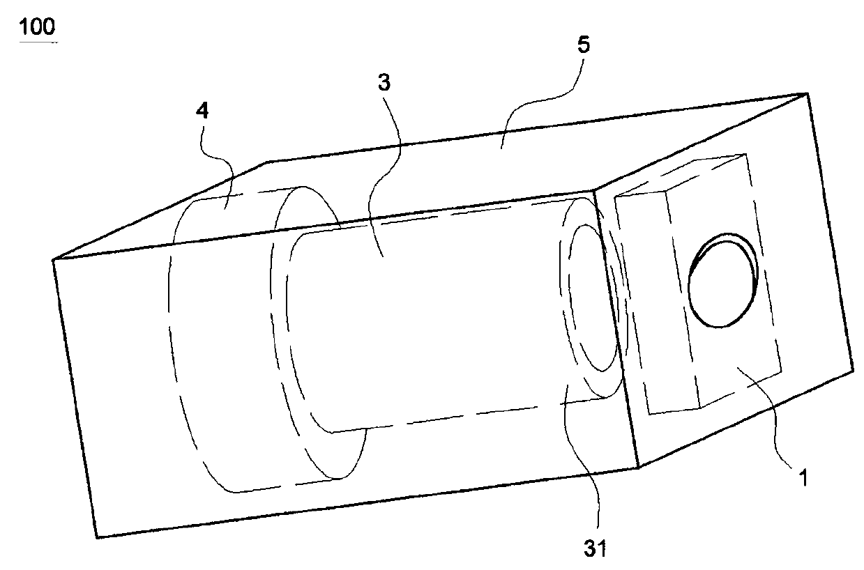
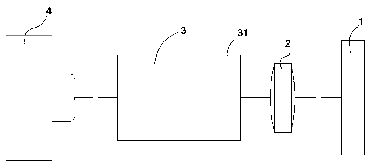
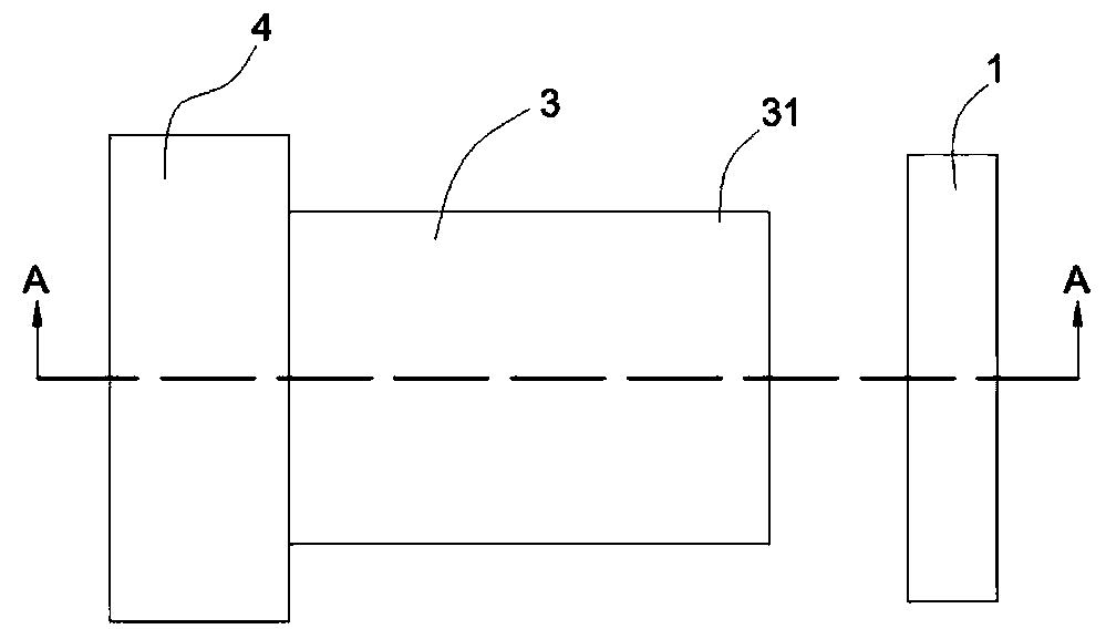
[0034] Such as Figure 1 to Figure 5 As shown, the aiming method of the barcode reader of the present invention (only the aiming device 100 of the barcode reader is shown in the accompanying drawings, the same below) includes the following steps:

[0035] Step 1: Preset a rectangular limit spot P (in order to facilitate the display of the shape of the limit spot P, attached Figure 5 And attached Figure 6 The limit light spot P in the image is black, and the barcode can be read normally in actual use; the influence of the limit light spot P on the reading of the barcode B can also be further reduced by laser blanking technology), the limit light spot P includes a limit Frame P1 and a cross spot P2 located in the very center ...


PUM


Abstract

The embodiment of the invention discloses a aiming method of a bar code reader and a aiming device thereof. The aiming device comprises a diffractive optical element (DOE), a lenticular lens, a collimating sleeve and a laser light source. Diffractive optical element (DOE), lenticular lens and laser light source are assembled in turn along the axis direction of the collimating sleeve; The laser generated by the laser light source passes through the lenticular lens and the diffractive optical element (DOE) in turn to generate a limiting light spot of a preset pattern, and the limiting light spotforms a limiting frame to guide the user to precisely frame and select the bar code to be read. The embodiment of the invention greatly improves the success rate of one-time code scanning, saves time, improves efficiency, and optimizes user experience. The limit frame can be used for selecting barcodes of various codes, and is suitable for reading 1D codes and 2D codes at the same time, which expands the application scope of the barcode reader.

Description

technical field [0001] The invention relates to an aiming method and an aiming device of a barcode reader, in particular to an aiming method and an aiming device of a barcode reader for frame-selecting barcodes. Background technique [0002] In order to facilitate scanning, the industry usually uses a barcode reading engine to project a positioning pattern on the barcode to guide users to aim at the barcode. [0003] Commonly used positioning patterns are a font and a cross. The one-shaped positioning pattern is only suitable for the reading and positioning of the one-dimensional code; the cross-shaped positioning pattern is more suitable for the reading and positioning of the two-dimensional code. People manufacture special-shaped lenses based on the principle of light diffraction (or refraction) To produce a cross-shaped positioning pattern, this kind of special-shaped lens has a large volume, which is not conducive to the miniaturization of components, and the assembly r...

Claims


Application Information

Patent Timeline
IPC IPC(8): G06K7/10
CPCG06K7/10831
Inventor 王冬生魏江涛张颂来刘惠
Owner SHENZHEN IDATA TECH CO LTD
Why Eureka
Try Eureka