A method for multi-focus image fusion

A multi-focus image and fusion method technology, applied in image enhancement, image analysis, image data processing, etc., can solve the problems of focusing and non-focusing boundary effects, unobtainable, easy to produce artificial effects, etc.

Pending Publication Date: 2019-03-26
NANCHANG HANGKONG UNIVERSITY
View PDF4 Cites 2 Cited by
  • Summary
  • Abstract
  • Description
  • Claims
  • Application Information

AI Technical Summary

Problems solved by technology

This type of method assumes that the saliency information of the original image can be extracted from these decomposed coefficients, and the fusion coefficient is obtained based on the comparison of the coefficients at the same position, so it is sensitive to image misregistration and is prone to artificial effects; spatial domain multi-focus image fusion The method generally obtains the confidence map first, and then uses the confidence map to combine the source image to obtain a fusion image, which is not sensitive to misregistration, but it usually causes the problem of focusing and non-focusing boundary effects due to the lack of accurate confidence map

Method used


Image

  • A method for multi-focus image fusion
  • A method for multi-focus image fusion
  • A method for multi-focus image fusion

Examples


specific Embodiment

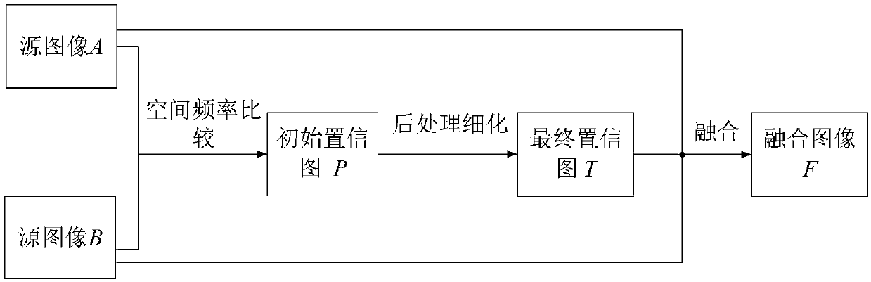
[0014] (1) Get the initial confidence map P

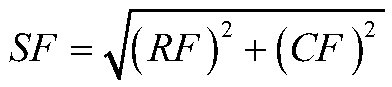
[0015] Our basic assumption for obtaining the initial confidence map is: the higher the spatial frequency value of the pixel, the clearer the corresponding position of the original image. For convenience, the spatial frequencies of the pixels of the source image A and B at position (x, y) are defined as A SF (x,y) and B SF (x,y). For an image I of size H×L, the pixel value of the pixel at position (x, y) is M(x, y), and the spatial frequency is defined as:

[0016]

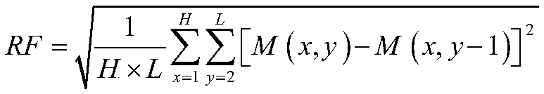
[0017] where the row frequency RF and column frequency CF are calculated as follows:

[0018]

[0019]

[0020] The steps to obtain the initial confidence map P are as follows:

[0021] Step1: Calculate the A of the source image A and B respectively SF (x,y) and B SF (x,y).

[0022] Step2: Compare the spatial frequency values ​​of the corresponding positions according to the following formula to obtain the initial confidence map P.

[0023]

[0024]...


PUM


Abstract

The invention discloses a multi-focus image fusion method, comprising the following steps: step 1, obtaining an initial confidence diagram P: firstly, obtaining the spatial frequency of each pixel ofa source image A and B, and then comparing the magnitude of the spatial frequency of the corresponding position, wherein the corresponding position with a larger value is set to 1, the corresponding position with a smaller value is set to 0, and finally obtaining 0-1 graph is the initial confidence graph P; 2, thin that initial confidence diagram P to obtain a final confidence diagram T: thinningthe initial confidence diagram P by mean of median filter, and then further thinning the initial confidence diagram P by small object removal measures to obtain a final confidence diagram T; 3, obtainthat fused image F: the final fuse image F is obtained by weighting and summing the final confidence graph T and the source image A and B. The invention can be insensitive to misregistration and caneffectively deal with the boundary effect problem between focusing and non-focusing.

Description

technical field [0001] The invention relates to the technical field of image fusion, in particular to a multi-focus image fusion method. Background technique [0002] In the field of digital photography, it is often difficult for an imaging device such as a digital single-lens reflex camera to take an image in which all objects are captured in focus. Typically, at a certain optical lens focal length setting, only objects within the depth of field (DOF) will have a sharp appearance in a photograph, while other objects will likely be blurred. Multifocus image fusion is a popular technique for fusing multiple images of the same scene taken with different focal length settings to obtain an all-in-focus image. In recent years, a variety of multi-focus image fusion methods have been proposed, which can be roughly divided into two categories: transform domain methods and space domain methods. The multi-focus image fusion method based on multi-scale transformation is the most typi...

Claims


Application Information

Patent Timeline
Patent Type & Authority Applications(China)
IPC IPC(8): G06T5/50G06T5/20
CPCG06T5/20G06T5/50G06T2207/20032G06T2207/20221
Inventor 鄢慧斌李忠民
Owner NANCHANG HANGKONG UNIVERSITY
Why Eureka
Try Eureka