Radiography system and image-processing method therefor
A technology of radiographic images and radiation, which is applied to the equipment used for radiological diagnosis, the use of radiation for material analysis, and the use of wave/particle radiation for material analysis, etc., which can solve problems such as image quality degradation
- Summary
- Abstract
- Description
- Claims
- Application Information
AI Technical Summary
Problems solved by technology
Method used
Image
Examples
no. 1 approach )
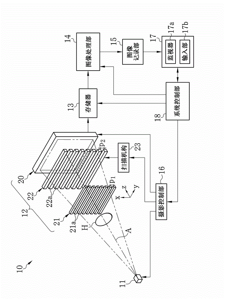
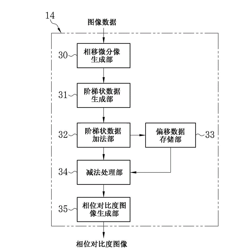
[0060] exist figure 1 Among them, the X-ray imaging system 10 according to the first embodiment of the present invention is provided with an X-ray source 11, an imaging unit 12, a memory 13, an image processing unit 14, an image recording unit 15, an imaging control unit 16, a console 17, and System control section 18. The X-ray source 1 irradiates the subject H with X-rays. The imaging section 12 is disposed facing the X-ray source 11 , and detects X-rays emitted from the X-ray source 11 and passing through the subject H to generate image data. The memory 13 stores image data read from the imaging unit 12 . The image processing section 14 performs image processing on a plurality of image data stored in the memory 13 to generate a phase contrast image. The image recording unit 15 stores the phase contrast image generated by the image processing unit 14 . The imaging control unit 16 controls the X-ray source 11 and the imaging unit 12 . The console 17 is provided with a m...
no. 2 approach )
[0137] In the first embodiment, when the distance between the X-ray source 11 and the FPD 20 is elongated, the influence of the blurring of the G1 image due to the focus size (usually 0.1mm to 1mm) of the X-ray focus 11a, the phase contrast The image quality of the image may deteriorate. In the second embodiment of the present invention, as Figure 15 As shown, a multi-slit (source grid) 60 is arranged on the emission side of the x-ray source 11 . The X-ray imaging system of the second embodiment is the same as that of the first embodiment except for the multi-slit 60 .
[0138] The multi-slit 60 is an absorption type grating having a similar configuration to the first absorption type grating 21 and the second absorption type grating 22 . The multi-slit 60 has a plurality of X-ray shielding portions 61 extending in the y direction and periodically arranged in the x direction. The multi-slit 60 partially shields the X-rays from the X-ray source 11 to reduce the effective foc...
no. 3 approach )
[0141] In the first and second embodiments, the first absorption type grid 21 is configured to linearly project X-rays passing through the X-ray low-absorption portion 21b. The present invention is not limited to this configuration. As disclosed in Japanese Patent No. 4445397, the first absorption type grid 21 may be configured to diffract X-rays to produce the so-called Talbot effect. In the third embodiment of the present invention, the first absorbing grating 21 is a diffraction grating and the distance L between the first absorbing grating 21 and the second absorbing grating 22 2 is set to the Talbot length to form a Talbot interferometer. In the present embodiment, the G1 image (self image) generated by the first grating 21 due to the Talbot effect is formed at the position of the second absorption type grating 22 .
[0142] In this embodiment, the first absorption type grating 21 may be a phase type grating (phase type diffraction grating). In this case, the thickness...
PUM
 Abstract
Description
Claims
Application Information
 - R&D
- Intellectual Property
- Life Sciences
- Materials
- Tech Scout
- Unparalleled Data Quality
- Higher Quality Content
- 60% Fewer Hallucinations
Browse by: Latest US Patents, China's latest patents, Technical Efficacy Thesaurus, Application Domain, Technology Topic, Popular Technical Reports.
© 2025 PatSnap. All rights reserved.Legal|Privacy policy|Modern Slavery Act Transparency Statement|Sitemap|About US| Contact US: help@patsnap.com


