Waveguide coaxial microstrip conversion circuit

A technology for converting circuits and microwave circuits, applied to circuits, waveguide devices, electrical components, etc., can solve the problems of microwave circuit sealing, failure to meet reliability requirements, and limit the maximum frequency of use, etc., to achieve simple structure and low cost , matching the effect of good

Inactive Publication Date: 2019-03-26
SOUTHWEST CHINA RES INST OF ELECTRONICS EQUIP
View PDF8 Cites 6 Cited by
  • Summary
  • Abstract
  • Description
  • Claims
  • Application Information

AI Technical Summary

Problems solved by technology

Rectangular waveguide can be directly converted to microstrip transmission line. The patent "Waveguide to Microstrip Transition Structure with Filtering Characteristics" (China, CN105576332A, 2016.05.11) realizes the conversion from waveguide to microstrip with filtering characteristics, but this direct conversion The method cannot realize the sealing of the microwave circuit and cannot meet the reliability requirements
In order to achieve sealing, coaxial insulators need to be used for transition. The patent "A Detachable Waveguide Coaxial Converter" (China, CN200953376Y, 2007.09.26) proposes a detachable waveguide coaxial converter for system debugging , can realize the conversion of waveguide to microstrip, and achieve sealing at the same time, but the purpose of this invention is to be detachable, so an SMA joint is added between the coaxial insulator and the rectangular waveguide, the structure is complicated, and the SMA joint limits the highest use of the invention frequency

Method used


Image

  • Waveguide coaxial microstrip conversion circuit
  • Waveguide coaxial microstrip conversion circuit
  • Waveguide coaxial microstrip conversion circuit

Examples


Embodiment Construction

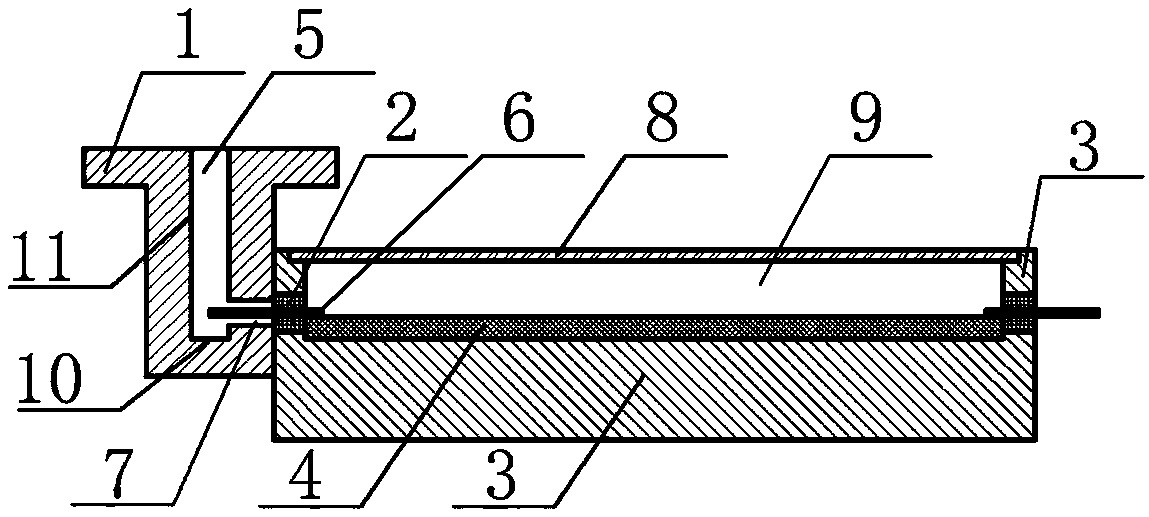
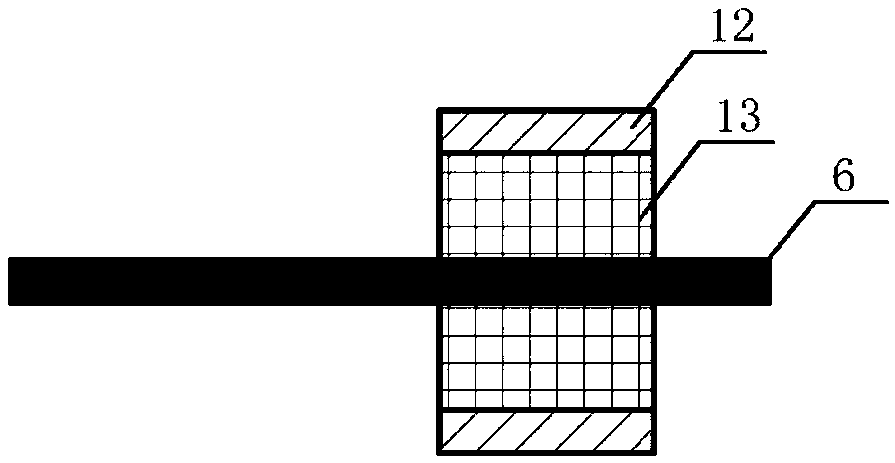
[0011] A waveguide coaxial microstrip conversion circuit, such as figure 1 and figure 2 As shown, it includes: rectangular waveguide connector 1, coaxial insulator 2, microwave circuit box body 3, microstrip circuit 4, waveguide cavity 5, inner conductor 6, through hole 7, cover plate 8, microwave cavity body 9, waveguide cavity bottom 10. Waveguide cavity side wall 11, outer conductor 12, insulating support structure 13, etc., wherein:

[0012] The present invention is generally composed of a rectangular waveguide connector 1 , a coaxial insulator 2 , a microwave circuit box 3 and a microstrip circuit 4 . The coaxial insulator 2 is composed of a coaxial cylindrical inner conductor 6 , an outer conductor 12 and an insulating support structure 13 , the inner conductor 6 passes through the middle of the insulating support structure 13 , and the outer conductor 12 is located outside the insulating support structure 13 . One end of the inner conductor 6 extends into the wavegui...


PUM


Abstract

The invention discloses a waveguide coaxial microstrip conversion circuit comprising a rectangular waveguide joint, a coaxial insulator, a microwave circuit box body and a microstrip circuit. The coaxial insulator comprises an inner conductor, an outer conductor and an insulating support structure. One end of the inner conductor passes through a through hole set in a waveguide wall to extend intoa waveguide cavity of the rectangular waveguide joint, and the other end of the inner conductor is connected to a microstrip line. A cover plate is arranged above the microwave circuit box body, and asealed microwave cavity is formed between the cover plate and the box body. According to the invention, one end of the inner conductor of the coaxial insulator passes extends into the cavity of the rectangular waveguide joint, the conversion of waveguide and coaxality is achieved, at the same time, the sealing performance requirement of the microwave circuit box body can be satisfied, the other end is connected to the microstrip line through a welding, bonding or crimping mode, the conversion of coaxality and the microstrip line is achieved, and the direction of a waveguide port is perpendicular to the direction of a microstrip transmission line. The rectangular waveguide joint can be disassembled and can be replaced with a coaxial connector for easy testing during commissioning.

Description

technical field [0001] The invention relates to a microwave circuit, in particular to a microwave signal waveguide coaxial microstrip conversion circuit. Background technique [0002] In order to obtain low insertion loss, rectangular waveguides are usually used to connect the antenna to the transmitter and receiver, while the transmitter and receiver including microwave solid-state circuits such as power amplifier chips and low-noise amplifier chips are integrated using microstrip transmission lines, so A rectangular waveguide to microstrip conversion circuit is needed. Rectangular waveguide can be directly converted to microstrip transmission line. The patent "Waveguide to Microstrip Transition Structure with Filtering Characteristics" (China, CN105576332A, 2016.05.11) realizes the conversion from waveguide to microstrip with filtering characteristics, but this direct conversion The method cannot realize the sealing of the microwave circuit, and cannot meet the reliabilit...

Claims


Application Information

Patent Timeline
Patent Type & Authority Applications(China)
IPC IPC(8): H01P5/103H01P1/06
CPCH01P1/06H01P5/103
Inventor 张建成
Owner SOUTHWEST CHINA RES INST OF ELECTRONICS EQUIP
Why Eureka
Try Eureka