AC/DC interconnected power grid continuous power flow model with VSC-MTDC

A technology of power flow model and interconnected power grid, which is applied to AC networks with different sources of the same frequency, power transmission AC networks, etc., and can solve the problems that cannot truly reflect the actual control behavior of VSC.

Active Publication Date: 2019-03-26
CHONGQING UNIV
View PDF5 Cites 15 Cited by
  • Summary
  • Abstract
  • Description
  • Claims
  • Application Information

AI Technical Summary

Problems solved by technology

[0006] 2) Simulation of active power control behavior of tie line transmission
[0008] 3) Accurate simulation of the control mode of the flexible DC transmission system
Therefore, the assumption that the PQ or PV control mode remains unchanged during the load growth process cannot truly reflect the actual control behavior of the VSC.

Method used


Image

  • AC/DC interconnected power grid continuous power flow model with VSC-MTDC
  • AC/DC interconnected power grid continuous power flow model with VSC-MTDC
  • AC/DC interconnected power grid continuous power flow model with VSC-MTDC

Examples


Embodiment 1

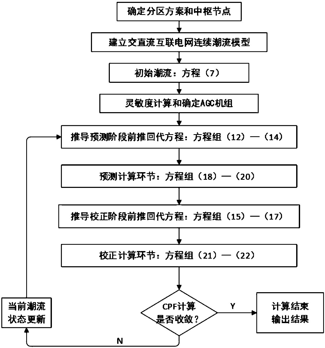
[0100] Such as figure 1 As shown, a continuous power flow model of AC-DC interconnected grid including VSC-MTDC mainly includes the following steps:

[0101] 1) Establish the power flow model of the multi-terminal flexible DC transmission system

[0102] 1.1) Build a multi-terminal flexible DC transmission system.

[0103] Further, in the multi-terminal flexible direct current transmission system, in the multi-terminal flexible direct current transmission system, the i1th converter is denoted as VSC i1 . The fundamental vector of the AC bus voltage at the boundary of the AC-DC system is denoted as The phase angle is denoted as δ ti5 . The fundamental wave vector of the output line voltage of the converter bridge is denoted as The phase angle is denoted as δ ci1 . x li1 and x ci1 are the fundamental reactances of the commutation reactor and the AC filter, respectively. R i1 is the equivalent resistance of the active loss of the converter bridge. P si1 with Q si...

Embodiment 2

[0179] A simulation test of a continuous power flow model of an AC-DC interconnected grid containing VSC-MTDC mainly includes the following steps:

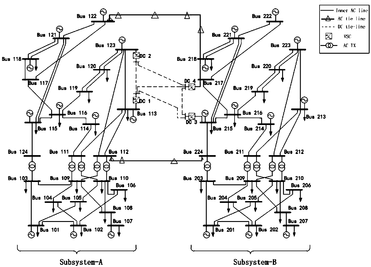
[0180] 1) The continuous power flow model of the AC-DC interconnected grid including VSC-MTDC is established in the two-area IEEE-RTS96 system, and the calculation program is written in the MATLAB environment.

[0181] The simulation network is attached figure 2 As shown, the following modifications are made on the basis of the original test system: Lines 113-215 and 123-217 are replaced by a four-port 300kV flexible DC network; two regional AC connection lines are added, namely lines 122-218 and 112 -224. In continuous power flow calculation, node 115 is used as the balance node of the whole network, and node 214 is used as the partition active power balance node.

[0182] The connection section is composed of AC connection lines 122-218, 112-224 and four-port flexible DC channels. The active power transaction constraint of t...


PUM


Abstract

The invention discloses an AC / DC interconnected power grid continuous power flow model with a VSC-MTDC. The main steps comprises the steps of (1) establishing a power flow model of a multi-terminal flexible DC and AC transmission systems, (3) establishing a control model of interconnected section transmission active power of the AC transmission system and the DC transmission system, (4) establishing an AC and DC interconnected power grid power flow model considering an interconnected section transmission active power constraints, (5) calculating the sensitivity K(g)<1> of all generator outputactive power to AC tie line transmission active power and determining an AGC unit and a unit of parameter load power incremental allocation according to the safety margin of the tie line transmissionactive power and K(g)<1>, and (6) obtaining a continuous power flow calculation result through four links of parametric equations, prediction, correction and step length adjustment. According to the AC / DC interconnected power grid continuous power flow model provided by the invention, an interconnected section active power market transaction constraint, a tie line transmission active control behavior and flexible DC power transmission system control mode are accurately simulated, and an effective guarantee is provided for the safety analysis and planning design of the power system operation.

Description

technical field [0001] The invention relates to the field of power system scheduling automation, in particular to a continuous power flow model of an AC-DC interconnected power grid including a VSC-MTDC. Background technique [0002] Continuous power flow method is a basic tool for static voltage stability analysis of power system. It has been widely used in safety analysis and planning design of power system operation, and has gradually become a core function of modern Energy Management System (EMS). With the continuous development of the modern power system, the modern power grid has gradually formed an AC-DC interconnected large power grid with ultra-high voltage, large capacity, and long-distance power transmission. Among them, the flexible DC transmission system has become one of the high-potential preferred solutions for regional tie lines due to its characteristics of decoupling control of active and reactive power, no commutation failure, and easy multi-terminal expa...

Claims


Application Information

Patent Timeline
Patent Type & Authority Applications(China)
IPC IPC(8): H02J3/36H02J3/06
CPCH02J3/06H02J3/36Y02E60/60
Inventor 颜伟丁冲田其生
Owner CHONGQING UNIV
Why Eureka
Try Eureka