
A communication system handover optimization method and system

A technology of a communication system and an optimization method, which is applied in the directions of wireless communication, electrical components, etc., to achieve the effects of improving the success rate of switching, improving storage, and improving utilization.

Active Publication Date: 2022-03-15
广州汇智通信技术有限公司
View PDF17 Cites 0 Cited by
  • Summary
  • Abstract
  • Description
  • Claims
  • Application Information

AI Technical Summary

Problems solved by technology

The underestimation of the role played by the core network and user terminals in the handover process has limited the research on handover technology.

Method used


Image

  • A communication system handover optimization method and system
  • A communication system handover optimization method and system
  • A communication system handover optimization method and system

Examples


Embodiment 1

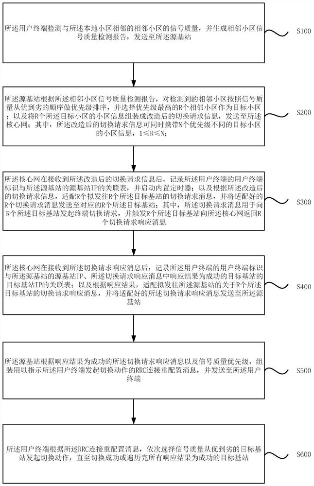
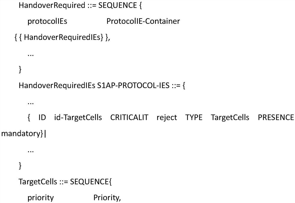
[0039] Please refer to the attached figure 1 , is a schematic flowchart of a communication system handover optimization method provided in Embodiment 1 of the present invention, the method is applicable to the scenario where a user terminal is handed over from one cell to another cell, and the method is executed by a communication system-based handover optimization system, so The communication system switching optimization system includes a user terminal, a source base station, a core network, and a target base station. The source base station manages the local cell where the user terminal is located, and the target base station manages the target cell where the user terminal intends to switch. The system It can be implemented by software and / or hardware, and integrated inside the mobile communication platform. The method specifically includes the following steps:

[0040] S100. The user terminal detects the signal quality of a neighboring cell adjacent to the local cell, gen...

Embodiment 2

[0085] Please refer to the attached figure 2 , is a schematic structural diagram of a communication system handover optimization system provided in Embodiment 2 of the present invention, and the system is suitable for implementing the communication system handover optimization method provided in the embodiment of the present invention. The system includes a user terminal 21, a source base station 22, a core network 23, and a target base station 24. The source base station 22 manages the local cell where the user terminal 21 is located, and the target base station 24 manages the target to which the user terminal 21 intends to switch. cell, the method comprising:

[0086] The user terminal 21 is configured to detect the signal quality of a neighboring cell adjacent to the local cell, and generate a signal quality detection report of a neighboring cell, and send it to the source base station 22;

[0087] Specifically, the message is sent to the source base station 22 by the fif...


PUM


Abstract

The present invention discloses a communication system handover optimization method and system. The method is realized by a communication system handover optimization system. The communication system handover optimization system includes a user terminal, a source base station, a core network and a target base station. The source base station management office The local cell where the user terminal is located, the target base station manages the target cell where the user terminal is to be handed over, by expanding the handover function of the core network and the user terminal, and on the basis of fully considering the air interface quality factors, the user terminal, The handover process between the source base station, the core network, and the target base station is integrated to a certain extent, which can not only improve the handover success rate and sequential handover rate, improve the storage and computing resource utilization of the base station, but also reduce the number of user terminals and base stations. The purpose of signaling interaction with the core network is to improve the utilization rate of the wireless channel on the user side and the limited channel between the source base station and the network side.

Description

technical field [0001] The embodiments of the present invention relate to the technical field of mobile communication, and in particular to a communication system handover optimization method and system. Background technique [0002] Anti-interference, anti-drop, mobility and other characteristics have always been the focus and difficulty of research in the field of mobile communication technology. The handover in the connected state is the focus of mobility management. The handover quality directly affects the user experience, so the research on handover is particularly important. [0003] Handover means that when a user terminal in a connected state moves from one cell to another, in order to ensure service continuity and a good user experience, communication system network elements such as user terminals, base stations, and core networks cooperate with each other. A series of signaling processes complete the process of terminal context switching and updating. [0004] A...

Claims


Application Information

Patent Timeline
Patent Type & Authority Patents(China)
IPC IPC(8): H04W24/02H04W36/00H04W36/08H04W36/30
CPCH04W24/02H04W36/0083H04W36/08H04W36/30
Inventor 王琪饶兵望黄伟朱文海
Owner 广州汇智通信技术有限公司
Learn More