Auxiliary clamping device of metallographic grinding and polishing machine

A clamping device, grinding and polishing machine technology, applied in the direction of grinding/polishing equipment, grinding machines, metal processing equipment, etc., can solve the problems of manual processing, time-consuming and labor-intensive grinding and polishing, etc., to achieve high grinding and polishing accuracy, Time saving, time saving effect

Pending Publication Date: 2019-03-29
ZHEJIANG UNIV OF TECH
View PDF0 Cites 5 Cited by
  • Summary
  • Abstract
  • Description
  • Claims
  • Application Information

AI Technical Summary

Problems solved by technology

Among these steps, the most time-consuming and laborious is the grinding and polishing in the sample preparation process, and these steps can only be processed manually. At this time, the grinding and polishing machine has become the gospel of the majority of material researchers.
[0005] However, the most common laboratory grinding and polishing equipment on the market requires manual operation, that is, manual clamping, and constant observation of the flatness of the sample and adjustment of the pressing force of the hand on the resin-embedded metal sample, which is time-consuming and labor-intensive. There is no guarantee that the processed samples can well meet the observation needs, and the gains outweigh the losses. It needs repeated repetitions, which is a great pain for researchers. Therefore, it is very necessary to design a set of auxiliary clamping devices for metallographic grinding and polishing machines. , which can liberate the hands of researchers, save the time of grinding and polishing samples, and at the same time ensure higher grinding and polishing precision. This device is of great significance to material researchers

Method used


Image

  • Auxiliary clamping device of metallographic grinding and polishing machine
  • Auxiliary clamping device of metallographic grinding and polishing machine
  • Auxiliary clamping device of metallographic grinding and polishing machine

Examples


Embodiment Construction

[0021] Below in conjunction with accompanying drawing, the patent of the present invention is further described.

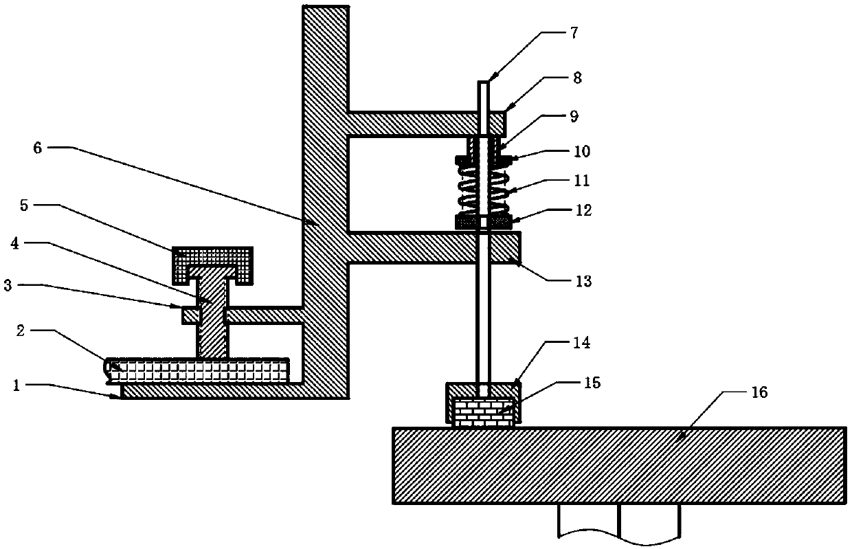
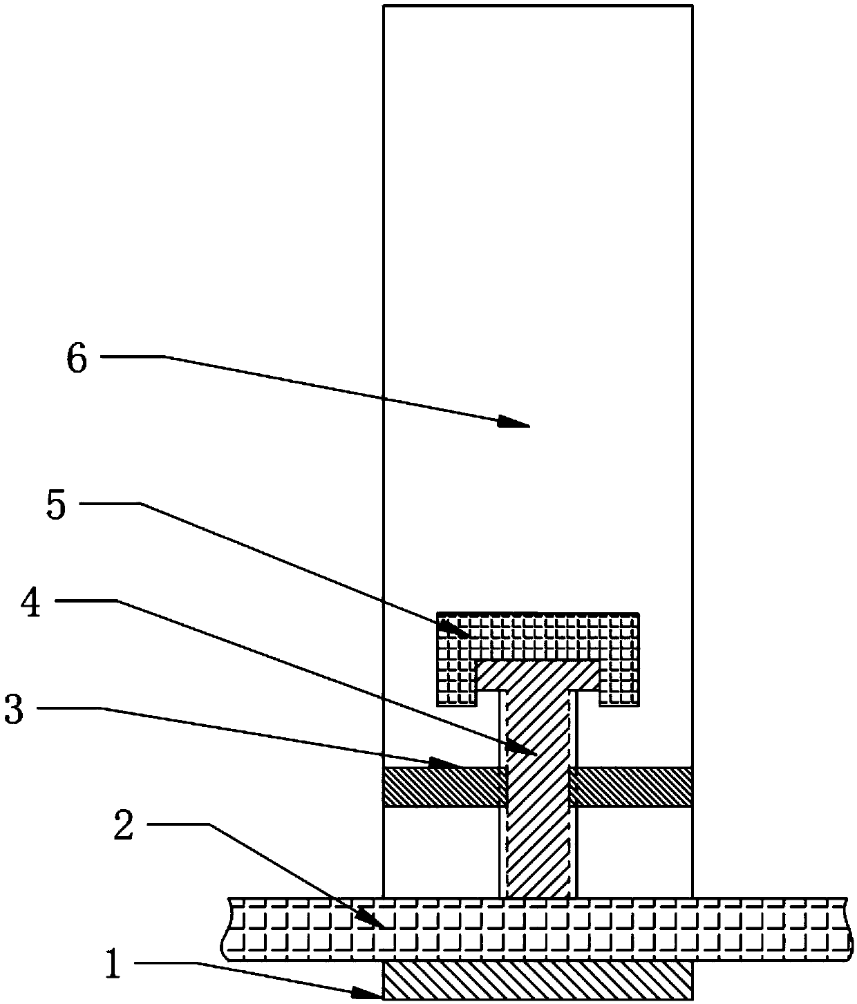
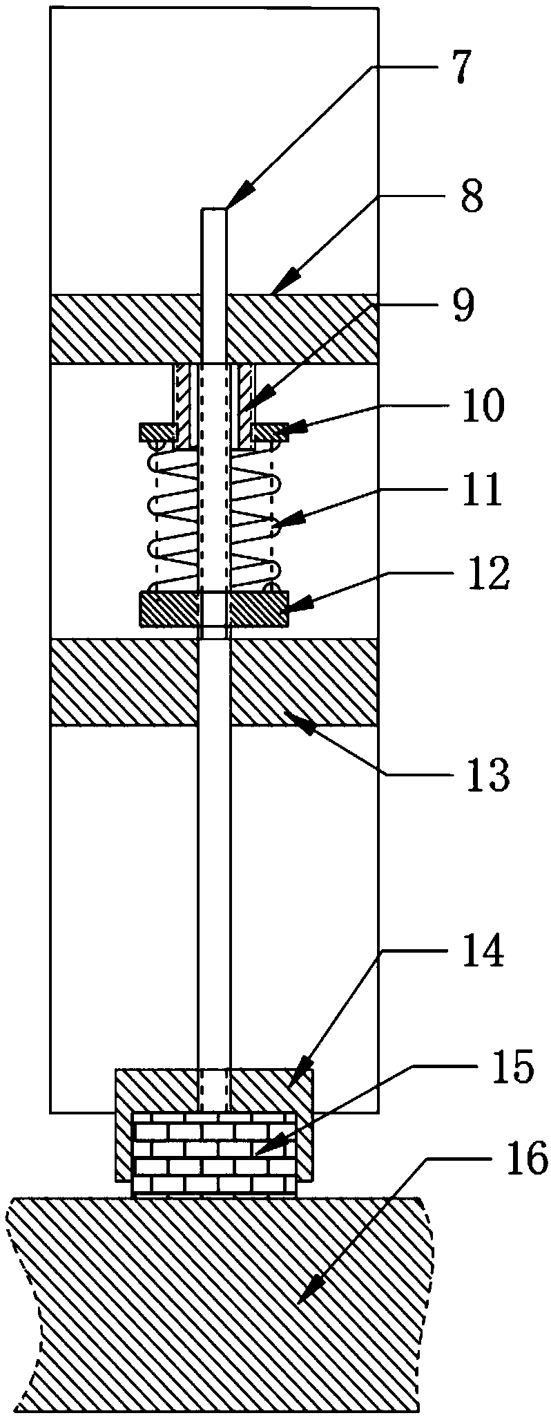
[0022] like figure 1 , the present invention is an auxiliary clamping device for a metallographic grinding and polishing machine, including a cage 6, fixing bolt assemblies 4 and 5, an externally threaded push rod 7, a force nut 10, a hard spring 11, a stop nut 12, a test Sample chuck 14 and other parts.

[0023] An auxiliary clamping device for a metallographic grinding and polishing machine, characterized in that it includes a vertical cage 6, the left side of the cage 6 is connected to the horizontal limit beam 3 and the bottom plate 1, and the bolt 4 is connected to the limit beam 3. The screw holes are engaged, and the lower end of the bolt 4 and the bottom plate 1 clamp the edge steel plate of the operation table of the grinding and polishing machine;

[0024] The right side of the cage 6 connects the upper slideway limit beam 8 and the glideway limit beam...


PUM


Abstract

The invention discloses an auxiliary clamping device of a metallographic grinding and polishing machine. The device comprises a vertical retainer, the left side of the retainer is connected with a horizontal limiting cross beam and a horizontal bottom plate, a bolt is meshed with a screw hole in the limiting cross beam, the lower end of the bolt and the bottom plate clamp an edge steel plate of anoperation table of the grinding and polishing machine; a first through hole in an upper slideway limiting cross beam and a second through hole in a lower slideway limiting cross beam are located on the same vertical line, an external thread push rod penetrates through the first through hole and the second through hole, the second through hole is a square hole, and the cross section of the external thread push rod at the second through hole is also of a square shape; the lower end of the external thread push rod is connected with a sample chuck, the sample chuck is fixedly connected with a resin block inlaid with a metallographic sample, and the bottom surface of the resin block is in contact with a grinding wheel of the grinding and polishing machine; and the outer wall of an external thread sliding sleeve on the bottom surface of the upper slideway limiting cross beam is meshed with a force application nut through threads, and a hard spring is arranged between the force application nut and a stop nut on the external thread push rod.

Description

technical field [0001] The invention belongs to the field of metal material science, specifically belongs to the field of metal material grinding and polishing processing technology, is an auxiliary facility for striving for grinding and polishing precision and flatness in the grinding and polishing process, and belongs to the supplementary design of traditional grinding and polishing equipment. technical background [0002] Metallographic analysis is one of the important means of experimental research on metal materials. Quantitative metallographic principles are used to determine the three-dimensional spatial morphology of the alloy structure by measuring and calculating the metallographic microstructure of the two-dimensional metallographic sample grinding surface or thin film, so as to establish Quantitative relationship between alloy composition, structure and properties. Applying the image processing system to metallographic analysis has the advantages of high precisio...

Claims


Application Information

Patent Timeline
Patent Type & Authority Applications(China)
IPC IPC(8): B24B19/00B24B41/06G01N1/28G01N1/32
CPCB24B19/00B24B41/06G01N1/28G01N1/32
Inventor 方炜田薇董豪炳李曰兵
Owner ZHEJIANG UNIV OF TECH
Why Eureka
Try Eureka