Mutually inserted rear auxiliary frame

A rear subframe and plug-in technology, which is applied to vehicle parts, substructure, transportation and packaging, etc., can solve the problems of multiple molds and fixtures, multiple installation procedures, and complex structures, so as to ensure production cycle and applicability Wider and reduce the effect of welding process

Pending Publication Date: 2019-03-29
BYD CO LTD
View PDF6 Cites 2 Cited by
  • Summary
  • Abstract
  • Description
  • Claims
  • Application Information

AI Technical Summary

Problems solved by technology

This technical solution consists of two longitudinal beams and front and rear beams, with many parts and complex structure, which indirectly leads to more molds and fixtures, more installation procedures, and the longitudinal beams and rear beams are fixed by nuts, which has poor fixability

Method used


Image

  • Mutually inserted rear auxiliary frame
  • Mutually inserted rear auxiliary frame
  • Mutually inserted rear auxiliary frame

Examples


Embodiment Construction

[0034] Embodiments of the present invention are described in detail below, examples of which are shown in the drawings, wherein the same or similar reference numerals designate the same or similar elements or elements having the same or similar functions throughout. The embodiments described below by referring to the figures are exemplary and are intended to explain the present invention and should not be construed as limiting the present invention.

[0035] The present invention will be described in detail below with reference to the accompanying drawings and examples.

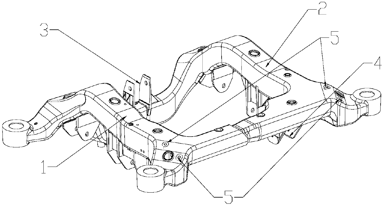
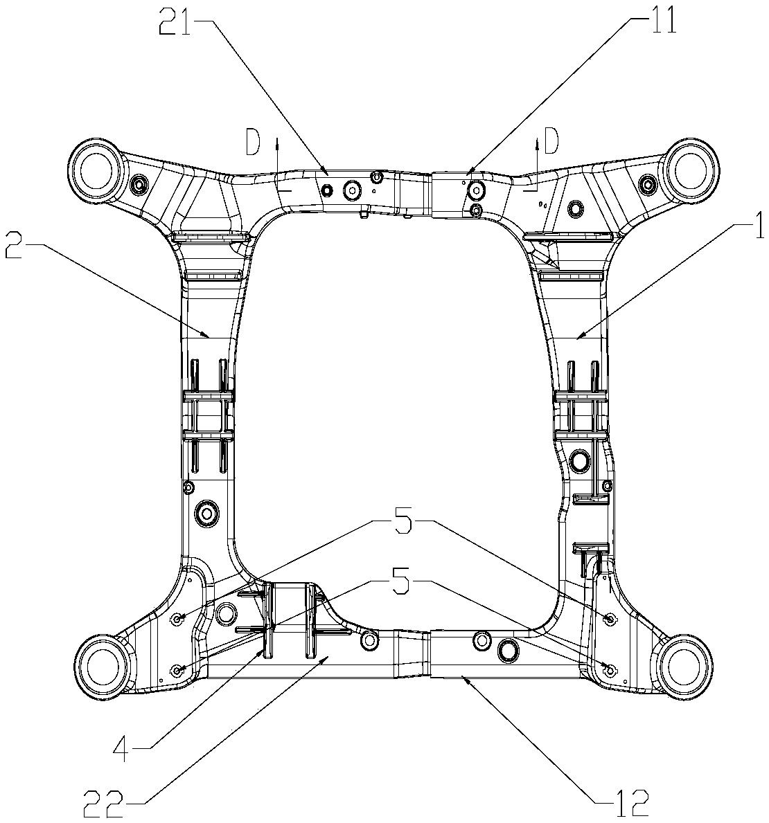
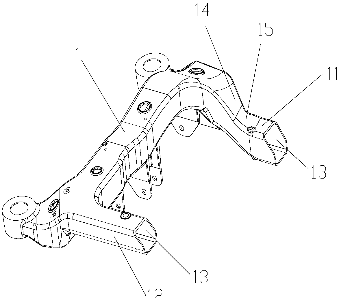
[0036] see figure 1 figure 2 As shown, the present invention discloses a plug-in rear sub-frame, which includes a left longitudinal beam 1 and a right longitudinal beam 2. The front and rear ends of the left longitudinal beam 1 are respectively extended transversely with a first front transverse beam facing the right longitudinal beam 2. section 11 and the first rear transverse section 12, and the front an...


PUM


Abstract

The invention discloses a mutually inserted rear auxiliary frame comprising a left longitudinal beam and a right longitudinal beam. A first front transverse section and a first rear transverse direction which face the right longitudinal beam horizontally extend from the front and rear ends of the left longitudinal beam respectively. A second front transverse section and a second rear transverse direction which face the left longitudinal beam horizontally extend from the front and rear ends of the right longitudinal beam respectively. The first front transverse section of the left longitudinalbeam and the second front transverse section of the right longitudinal beam are inserted into each other to form a front cross beam. The first rear transverse section of the left longitudinal beam andthe second rear transverse section of the right longitudinal beam are inserted into each other to form a rear cross beam. The rear auxiliary frame is formed by inserting and welding the left and right longitudinal beams to each other, has less parts, reduces mold development, has less welding points, is convenient to machine, and can reduce the influence of welding heat on the aluminum alloy materials of the left and right longitudinal beams. The length of the butt joint portion of the left and right longitudinal beams can be adjusted to adjust the length of the front cross beam in order thatthe rear auxiliary frame adapts to different vehicle models and different wheel tracks, realizing a platformized and generalized chassis, and reducing the development cost of the new vehicle.

Description

technical field [0001] The invention relates to a vehicle rear auxiliary frame structure, in particular to a plug-in rear auxiliary frame. Background technique [0002] The performance of the car chassis is nothing more than the two themes of comfort and handling, and these two themes are a pair of contradictions that restrict each other. The traditional suspension system can usually only be adjusted in one direction, that is, the suspension system that focuses on handling will inevitably lose some comfort performance, and the suspension that focuses on comfort will inevitably affect some handling performance. In order to achieve a balance between comfort and handling, some equipment and designs that have a greater impact on comfort and handling have also emerged as the times require. The subframe is a typical representative. [0003] At present, most of the sub-frames are generally four beams connected by welding to form a frame structure, and each beam is welded by upper...

Claims


Application Information

Patent Timeline
IPC IPC(8): B62D21/02
CPCB62D21/02
Inventor 卢艺孙为州孙宪猛杨哲姚渊
Owner BYD CO LTD
Why Eureka
Try Eureka