Novel chemical material barrel

A material barrel and chemical technology, which is applied in chemical instruments and methods, chemical/physical processes, mixers, etc., can solve the problems of extrusion deformation of chemical material barrels, long standing time, and vulnerability to collision and extrusion of other items. Achieve the effect of simple structure and guaranteed mixing quality

Active Publication Date: 2019-03-29
江苏广域化学有限公司
View PDF9 Cites 2 Cited by
  • Summary
  • Abstract
  • Description
  • Claims
  • Application Information

AI Technical Summary

Problems solved by technology

[0009] The invention provides a new type of chemical material barrel through improvement. The power cord at the rear end of the motor is inserted into the front socket of the lithium battery. The lithium battery provides electric energy for the motor, and then the motor rotates through the coupling to drive the rotation shaft at the right end. The rotation drives the first worm wheel and the second worm wheel to rotate at the same time, so that the two sets of first agitator and the second agitator at the bottom rotate, and then the first agitator and the second agitator rotate to stir the chemical solution and materials inside the tank, which is beneficial to the chemical industry. The solution and materials are stirred. The first agitator is composed of nine sets of composite paddle-type stirring blades. The composite-blade paddle-type stirring blades have a simple structure and are welded by two blades. During the stirring process, radial At the same time, the second agitator at the bottom fully mixes the chemical solution and the material, which ensures the mixing quality and solves the problem that the internal chemical solution and the material stand for too long during the long-term transportation of the chemical tank, which leads to the separation of the material and the chemical solution Precipitation affects the quality of storage; lift the barrel body and move it to the top surface of the second fixed block. Since the bottom end of the chassis is equipped with a connecting frame, move the through hole on the bottom end of the connecting frame to the top of the second fixed block. The threaded hole is used to fix the left and right sides of the bottom end of the connecting frame with the inner threaded holes on the left and right inner sides of the top of the second fixed block through bolts, so that the barrel body is fixed on the inner diameter of the protection bracket, and the barrel body structure is protected from being squeezed by external objects , to solve the problem that the chemical material tank is easily collided and squeezed by other objects during logistics transportation, resulting in the extrusion deformation of the chemical material tank, and the problem that the internal solution of the chemical material tank is easy to leak; before using the protective bracket, put the inner rod outside the left end Insert the inner side of the right end of the outer rod, and adjust the distance between the inner rod and the outer rod to be larger than the diameter of the barrel body. Overlap on the top of the inner threaded hole, then pass the connecting bolt through the mounting hole and the inner threaded hole, and then rotate and tighten the connecting bolt to fix the distance between the inner rod and the outer rod, so as to adjust the width of the protective bracket and provide different capacities. The beneficial effect of the use of chemical tanks solves the problem that a single protective frame can only fix a single item during use, which is inconvenient during use, resulting in the need to customize a separate protective frame for chemical tanks with different capacities, which not only increases The problem of lowering the cost and single usability

Method used


Image

  • Novel chemical material barrel
  • Novel chemical material barrel
  • Novel chemical material barrel

Examples


Embodiment Construction

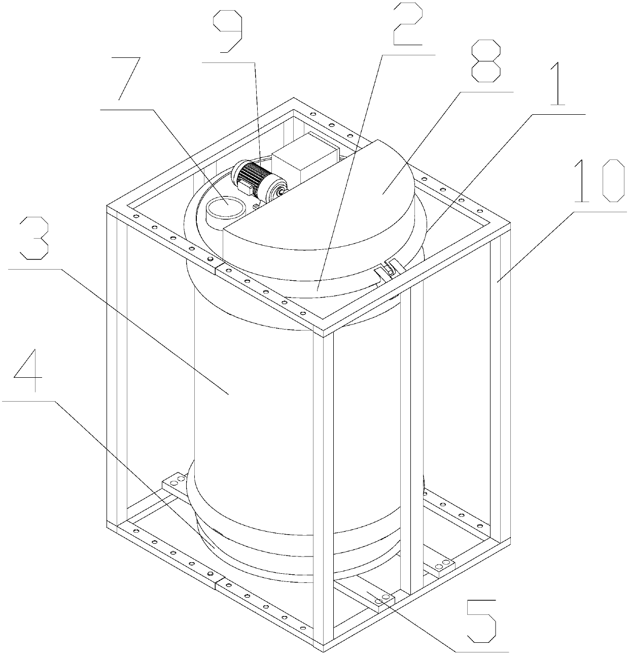
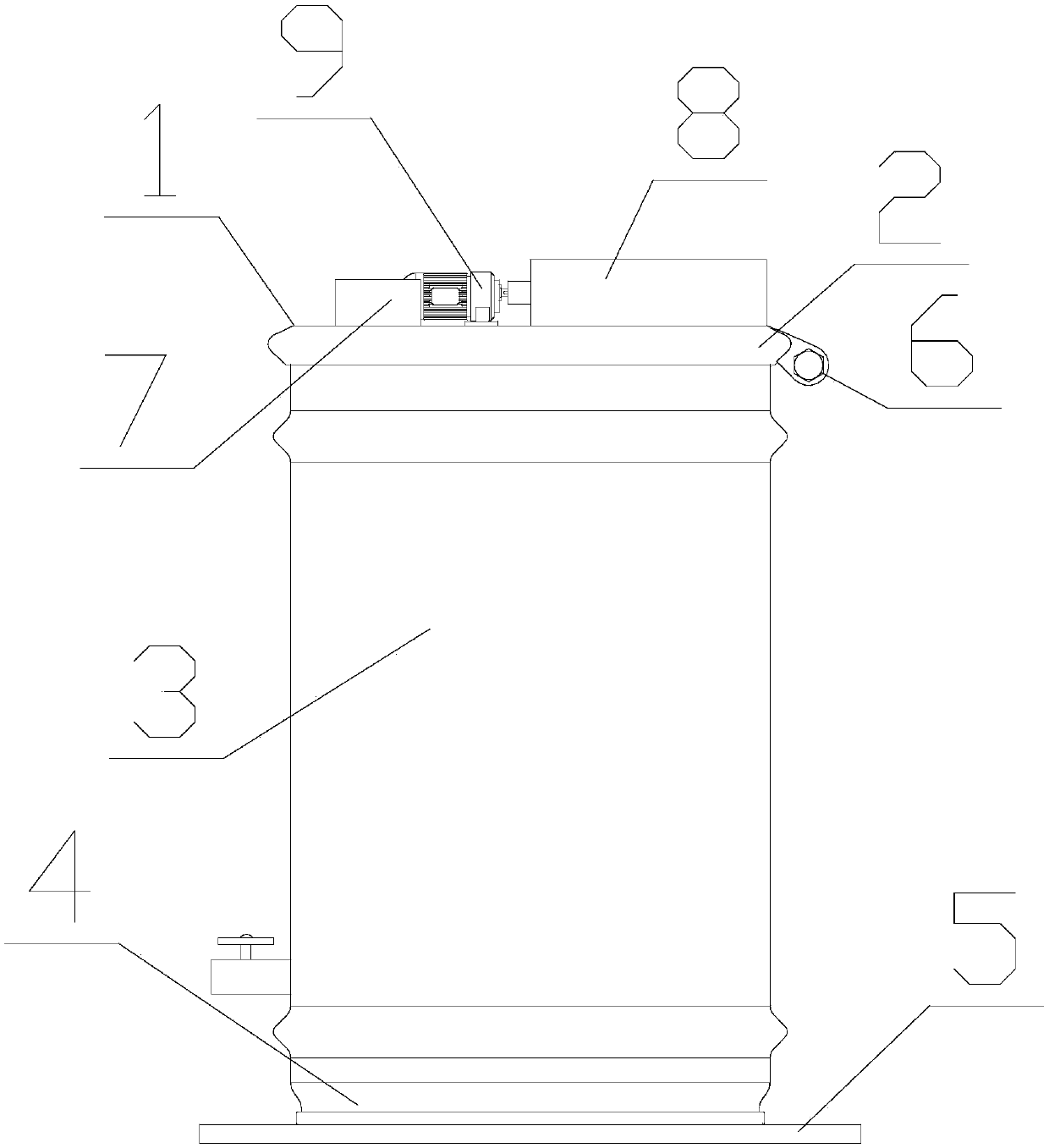
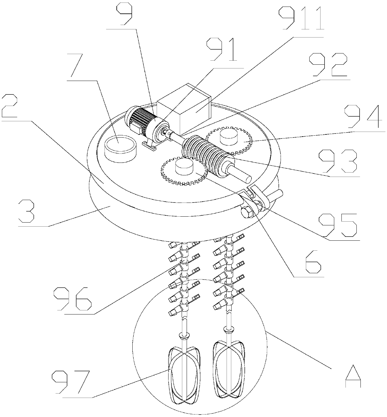
[0040] The following will be combined with Figure 1-7 The present invention is described in detail, and the technical solutions in the embodiments of the present invention are clearly and completely described. Apparently, the described embodiments are only some of the embodiments of the present invention, not all of them. Based on the embodiments of the present invention, all other embodiments obtained by persons of ordinary skill in the art without making creative efforts belong to the protection scope of the present invention.

[0041] The present invention provides a new type of chemical tank through improvement, including a tank body 1, a bucket cover 2, a jar 3, a chassis 4, a connecting frame 5, a connecting piece 6, a connecting pipe 7, a protective cover 8, a stirring device 9 and Protective bracket 10, barrel body 1 top surface is provided with barrel cover 2, and barrel body 1 top surface is parallel to barrel cover 2 top surface, and barrel cover 2 inner diameter i...


PUM


Abstract

The invention discloses a novel chemical material barrel. The novel chemical material barrel comprises a material barrel body, a barrel cover, a can, a base plate, a connecting frame, a connecting piece, a connecting pipe, a protective cover, a stirring device and a protective support, the barrel cover is arranged on the top end surface of the material barrel body, moreover, the top end surface ofthe material barrel body is parallel to the top end surface of the barrel cover, and the inner diameter of the barrel cover is the same as the outer diameter of the top end surface of the can in size. The material barrel body is lifted up and moved to the top end surface of a second fixing block, due to the fact that the connecting frame is arranged on the bottom end surface of the base plate, through holes in the bottom end surface of the connecting frame are moved to inner threaded holes in the top end of a second fixing block, the left side and the right side of the bottom end surface of the connecting frame are fixed to the inner threaded holes in the left inner side and the right inner side of the top end of the second fixing block through bolts, then the material barrel body is fixed to the inner diameter of the protective support, the structure of the material barrel body is protected, the chemical material barrel is prevented from being extruded by external objects, and the problem that when logistics transportation is performed, the chemical material barrel is prone to be impacted and extruded by other objects, so that the chemical material barrel is deformed because of bearing extrusion, and a solution inside the chemical material barrel is prone to leaking is solved.

Description

technical field [0001] The invention relates to the related fields of chemical material barrels, in particular to a novel chemical material barrel. Background technique [0002] Chemical barrels are tools used in chemicals, dyes, medicines, and pesticides. Most chemical barrels are made of plastic and steel. In the processing of chemical products, some materials need to be stored. Chemical barrels are often batched during transportation. Stacked or transported together with other sundries, the outer wall of the steel chemical tank is soft, and it is easy to deform and leak when subjected to external extrusion. Therefore, a chemical tank with high structural strength and not easy to bend is urgently needed on the market. [0003] However, the existing novel chemical tanks have the following problems: [0004] 1. In the existing new type of chemical material tank, during the long-term transportation of the chemical material tank, the internal chemical solution and the materia...

Claims


Application Information

Patent Timeline
Patent Type & Authority Applications(China)
IPC IPC(8): B65D51/32B65D25/20B01F7/00B01F7/18
CPCB65D25/20B65D51/32B01F27/192B01F27/90
Inventor 陈鹏
Owner 江苏广域化学有限公司
Why Eureka
Try Eureka