
Mobile blood bank

A blood bank and blood bag technology, applied in the field of mobile blood banks, can solve problems such as cross-matching blood, lack of personnel and equipment in hospital blood banks, and impact on storage, and achieve the effects of avoiding blood bag damage, good refrigeration effect, and reducing blood waste

Pending Publication Date: 2019-03-29
深圳市大汇通医疗科技有限公司
View PDF0 Cites 4 Cited by
  • Summary
  • Abstract
  • Description
  • Claims
  • Application Information

AI Technical Summary

Problems solved by technology

Each hospital stores a certain proportion of blood according to the needs of the actual hospital. The stock of blood is insufficient, and it is impossible to add a secondary warehouse in the clinical department. The hospital blood bank has insufficient personnel and equipment, and cannot perform cross-matching and blood distribution in the clinical department according to clinical needs. Blood can only be matched and issued in a centralized blood bank
[0006] Based on the above analysis, it can be seen that the application of mobile blood banks is an inevitable trend. In the existing mobile blood banks, the blood storage cabinet usually has only one opening. When taking blood, other blood is also in contact with the external environment at the same time. The storage period will be shortened, especially in summer or when the external ambient temperature is high, the upper part of the stored blood will be denatured quickly, which will affect the storage; at the same time, in the existing mobile blood bank, the relationship between the blood bag and the storage device is not considered. Shock absorption and cushioning problems, the blood bag is likely to be damaged during the movement of the mobile blood bank, resulting in unnecessary waste of blood; the existing storage structure has poor refrigeration effect

Method used


Image

  • Mobile blood bank
  • Mobile blood bank
  • Mobile blood bank

Examples


Embodiment Construction

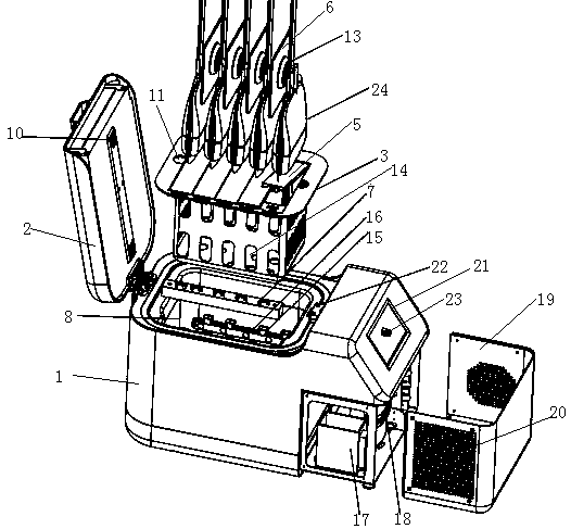
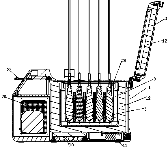
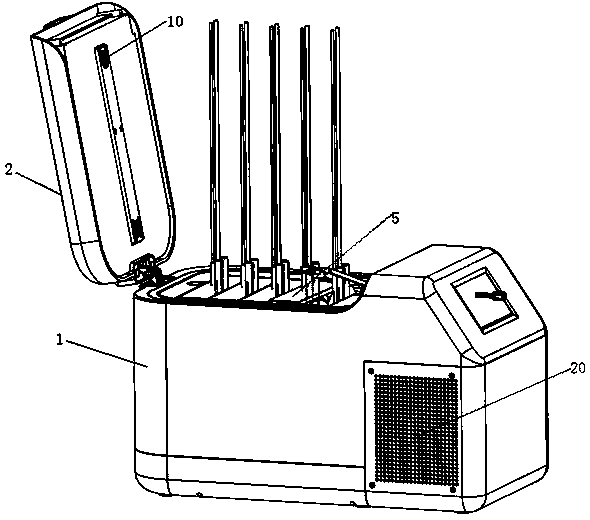
[0055] Such as Figure 1 ~ Figure 3 As shown, the present invention includes a casing 1; the top surface of the casing 1 is open, and one side of the top surface is hinged to the cover body 2; a blood bag storage box is arranged inside the casing 1, and the blood bag storage box includes an inner Lining 3; the upper surface of the lining 3 is open, and the opening is covered by a cover plate 4; the cover plate 4 is evenly divided into N covering units 5 along the length direction, and the same end of the N covering units All are hinged to one side of the cover plate 4, N≥1; N-1 partitions 6 are arranged in the inner lining 3, and the distance between two adjacent partitions 6 is the same as that of the cover unit 5; the four edges of the upper surface of the inner lining 3 are all beyond the lower part of the inner lining 3, and N installation holes are opened on one of the edges; one end of the covering unit 5 near the installation hole is lower There are protrusions on the ...


PUM


Abstract

The invention discloses a mobile blood bank. The mobile blood bank includes a shell. The top surface of the shell is open. One side edge of the top surface is hinged to a cover. A blood bag storage box is arranged in the shell. The blood bag storage box includes an inner liner. An opening is arranged in the upper surface of the inner liner. The opening is covered by a cover plate. The cover plateis evenly divided into N cover units along the length direction, and the same ends of the N cover units are hinged to one side of the cover plate, wherein N>=1. N-1 separating plates are arranged in the inner liner. The distance between the two adjacent separating plates match the width of the cover units. The four edges of the upper surface of the inner liner are all beyond the lower part of theinner liner. One of the edges is provided with N mounting holes. A protrusion is arranged on the lower surface of one end, being close to the corresponding mounting hole, of each cover unit. One sideedge of the upper surface of the shell is provided with N light touch switches. The mobile blood bank can avoid changing the storage environment in the storage box when taking blood to ensure good refrigeration effect.

Description

technical field [0001] The invention relates to the field of blood storage, in particular to a mobile blood bank. Background technique [0002] Whole blood and red blood cell suspension should be stored at 4±2°C for 35 days, virus-inactivated plasma should be stored below -20°C for 1 year, and machine-collected platelets should be stored at 22±2°C for 5 days with shaking. The storage environment of all the above blood products needs to be monitored 24 hours a day. It usually takes 30-60 minutes for the blood to be sent from the hospital blood bank to the start of infusion. For cases where more than 2 bags of blood are taken at a time, the second bag of blood will be exposed to room temperature for a longer period of time. At present, there are various forms and materials of liquid collection boxes in clinical use, and there is no uniform standard and detailed usage method, resulting in the lack of uniform standards for blood transportation. At present, some blood collectio...

Claims


Application Information

Patent Timeline
Patent Type & Authority Applications(China)
IPC IPC(8): B65D81/18B65D81/38B65D81/05B65D43/16B65D25/14B65D25/02B65D25/04B65D53/02F25D23/00F25D31/00
CPCF25D23/006F25D31/005B65D25/02B65D25/04B65D25/14B65D43/164B65D53/02B65D81/05B65D81/18B65D81/3823
Inventor 潘松成陈金榜
Owner 深圳市大汇通医疗科技有限公司
Learn More