Glue and manufacturing method thereof, optical element and manufacturing method thereof, and display device

An optical element and manufacturing method technology, applied in the directions of adhesives, instruments, etc., can solve the problems of uneven distribution of alignment films, poor display effect of display devices, poor light splitting effect of visual separation elements, etc., so as to improve the display effect and improve the light splitting effect. Effect

Active Publication Date: 2021-04-20
ZHANGJIAGANG KANGDE XIN OPTRONICS MATERIAL
View PDF2 Cites 0 Cited by
  • Summary
  • Abstract
  • Description
  • Claims
  • Application Information

AI Technical Summary

Problems solved by technology

At present, in the production process of the visual separation element, due to the difference in the surface morphology of the prisms after the lenticular lens array is formed, when the alignment film is coated in the subsequent process, the alignment film material flows and gathers at the bottom of the three-dimensional structure of the lenticular lens array, so that the alignment film The distribution in the three-dimensional structure of the lenticular lens array is not uniform, resulting in poor light splitting effect of the final formed visual separation element, so that the display effect of the display device is poor

Method used


Image

  • Glue and manufacturing method thereof, optical element and manufacturing method thereof, and display device
  • Glue and manufacturing method thereof, optical element and manufacturing method thereof, and display device
  • Glue and manufacturing method thereof, optical element and manufacturing method thereof, and display device

Examples


Embodiment Construction

[0045] The present invention will be further described in detail below in conjunction with the accompanying drawings and embodiments. It should be understood that the specific embodiments described here are only used to explain the present invention, but not to limit the present invention. In addition, it should be noted that, for the convenience of description, only some structures related to the present invention are shown in the drawings but not all structures.

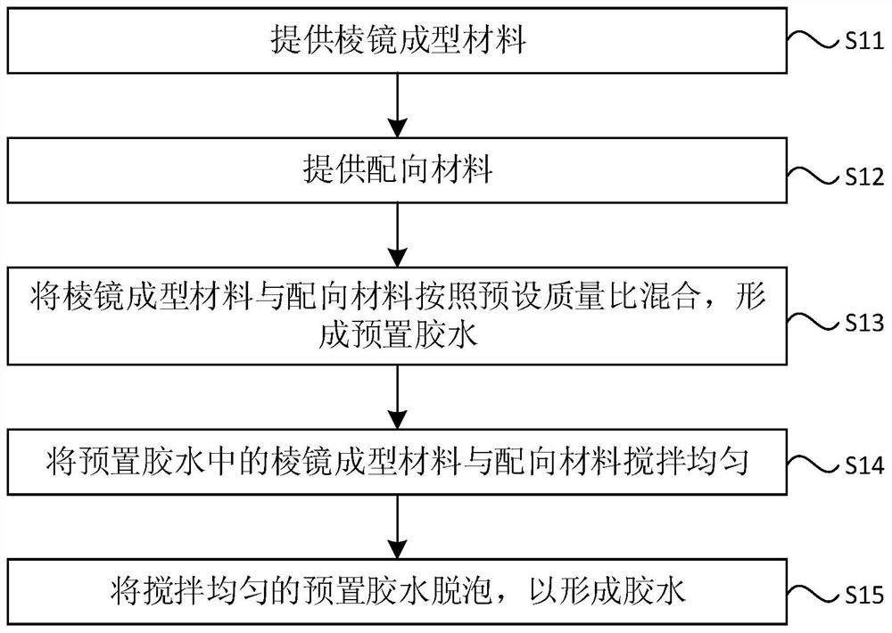
[0046] figure 1 It is a schematic flow chart of a method for making glue provided by an embodiment of the present invention. refer to figure 1 , the preparation method of this glue comprises:

[0047] S11. Provide prism molding materials.

[0048] Among them, the prism molding material is only used to form a lenticular lens array in the existing manufacturing process, but does not have alignment performance.

[0049] Exemplarily, the prism forming material may be thermosetting glue, light curing glue or other ...


PUM


Abstract

The invention discloses a glue and a manufacturing method thereof, an optical element, a manufacturing method thereof and a display device. The method for making the glue includes: providing a prism forming material; providing an alignment material; mixing the prism forming material and the alignment material according to a preset mass ratio to form a preset glue; stirring the prism forming material and the alignment material in the preset glue evenly; Degas the pre-mixed pre-glue to form the glue. The technical solution provided by the present invention can form the alignment layer while forming the lenticular lens array with glue, without the need to coat the alignment film after the lenticular lens array is formed, thereby avoiding the accumulation of the alignment film material at the bottom of the three-dimensional structure of the lenticular lens array. The resulting uneven distribution of the alignment film in the three-dimensional structure of the lenticular lens array can improve the light-splitting effect of the view-separation element, thereby improving the display effect of the display device.

Description

technical field [0001] The embodiments of the present invention relate to the technical field of test fixtures, and in particular to a glue and a manufacturing method thereof, an optical element and a manufacturing method thereof, and a display device. Background technique [0002] With the development of display technology, the display effect of the display device is transitioning from planar (two dimensional, 2D) display to stereoscopic (three dimensional, 3D) display. Stereoscopic display technology has become a new development trend in the field of display technology, and more and more display devices begin to integrate the stereoscopic display technology. And in order to improve user experience, naked-eye stereoscopic display technology has gradually become a research hotspot. The basic principle of the naked-eye stereoscopic display technology is to use occlusion, refraction, etc. to make the left and right eyes see pictures with parallax information, thereby generati...

Claims


Application Information

Patent Timeline
IPC IPC(8): C09J201/00C09J179/08G02B30/28
CPCC09J201/00G02B30/27C08L79/08
Inventor 袁鑫黄永辉
Owner ZHANGJIAGANG KANGDE XIN OPTRONICS MATERIAL
Why Eureka
Try Eureka