Kitchen oil smoke purification device and method for catering industry

A technology of oil fume purification and equipment, which is applied in chemical instruments and methods, oil fume removal, separation methods, etc., can solve problems such as air pollution, large oil fume emission density and discharge volume, and large fire safety hazards, and achieve the effect of efficient purification effect

Pending Publication Date: 2019-03-29
北京创新环科环保科技有限公司
View PDF0 Cites 1 Cited by
  • Summary
  • Abstract
  • Description
  • Claims
  • Application Information

AI Technical Summary

Problems solved by technology

The exhaust fan can only exhaust the cooking fume, but it cannot solve the pollution of the whole air and the kitchen operation room caused by the cooking fume pollutants. The cooking fume contains many substances harmful to the human body. Working in a room full of oily fumes can lead to many diseases. Oily fume pollutants in the catering industry are already one of the main sources of air pollution, and the relative density and emission of oily fumes from enterprises, institutions, schools, and other canteens and commercial catering The amount is larger, causing great pollution to the atmosphere, and it is one of the main sources of air pollutants PM2.5 and PM1
And because the temperature of the flue gas produced by the stove cooking is very high, after a long period of use, the high-temperature oil fume is likely to cause the combustion of grease pollutants deposited in the exhaust channel, causing a great fire safety hazard
[0004] The current oil fume purification equipment in the kitchen of the catering industry still has the problem that the purification effect of the oil fume cannot meet the relevant emission standards and the unavoidable safety hazards of causing fires

Method used


Image

  • Kitchen oil smoke purification device and method for catering industry
  • Kitchen oil smoke purification device and method for catering industry
  • Kitchen oil smoke purification device and method for catering industry

Examples


Embodiment Construction

[0028] A specific embodiment of the present invention will be described in detail below in conjunction with the accompanying drawings, but it should be understood that the protection scope of the present invention is not limited by the specific embodiment.

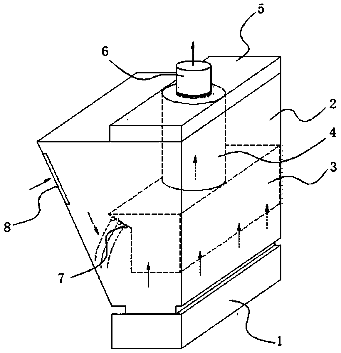
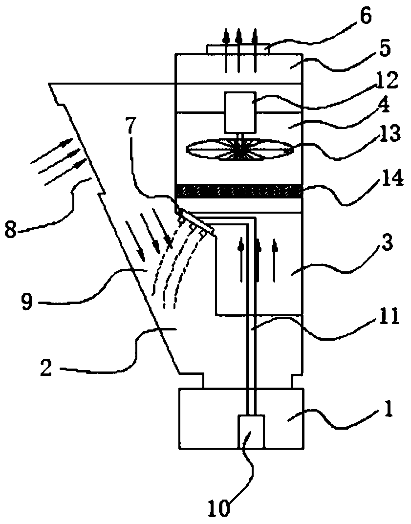
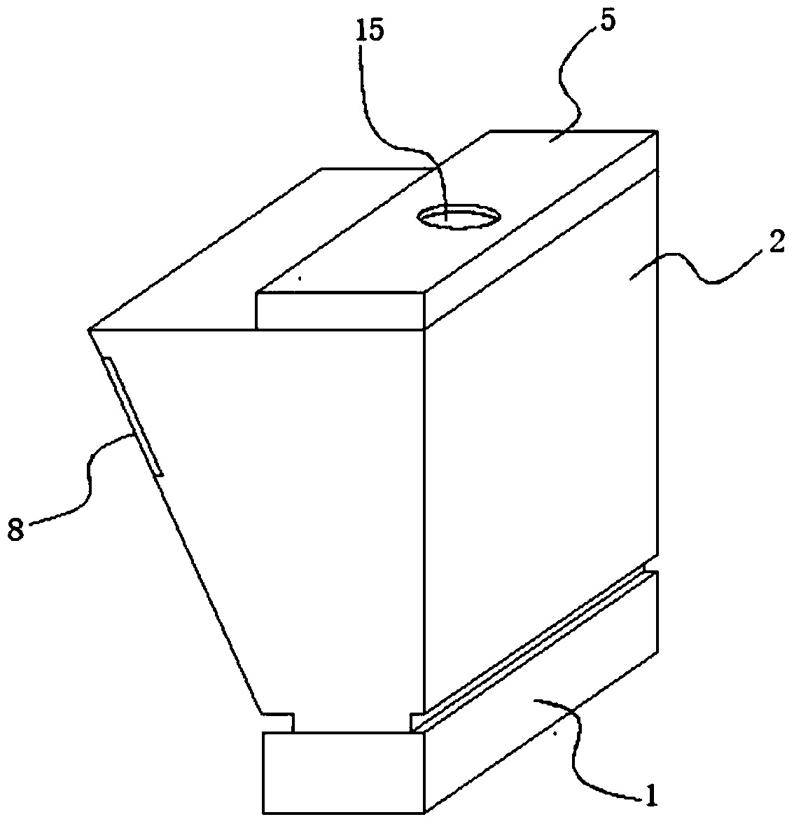
[0029] Such as figure 1 and figure 2 As shown, a cooking oil fume purification equipment for the catering industry provided by the embodiment of the present invention includes a water storage tank 1 on which a purification tank 2 is fixed, and the purification tank 2 is an inverted right-angled trapezoidal structure. A flow-limiting box 3 is fixed inside the box 2, and a delivery cylinder 4 is fixedly connected to the flow-limiting box 3, and an exhaust joint 6 is connected to the upper end of the delivery cylinder 4, and the inclined surface of the purification box 2 is connected with the flow-limiting An air flow channel 9 is left between the boxes 3, and a spray device 7 for covering the air flow channel 9 is fixed on...


PUM


Abstract

The invention discloses kitchen oil smoke purification device and method for the catering industry. The device comprises a water storage tank, a purification tank is fixed to the water storage tank and is of an inversely right-angular ladder-shaped structure, a flow limiting tank is fixed in the purification tank, and the upper end of the flow limiting tank is fixedly connected with a conveying cylinder; an exhausting connector is in threaded connection with the upper end of the conveying cylinder, an overhaul port is formed in the purification box, a detachable end cover is fixed to the overhaul port, a limiting through hole for the exhausting connector to penetrate through is formed in the end cover, and an air flow channel is reserved between the inclined surface of the purification boxand the flow limiting box; a spraying device for covering the air flow channel is fixed to the outer side wall of the flow limiting box, a motor is fixed in the conveying cylinder, a centrifugal meshdisc is coaxially fixed to the output end of the motor, and an oil smoke filter screen is mounted at the portion, below the purification net disc, in the conveying cylinder. The device can achieve ahigh-quality purification effect on kitchen oil smoke.

Description

technical field [0001] The invention relates to the field of oil fume purification and filtration in the catering industry, in particular to a kitchen oil fume purification equipment and method in the catering industry. Background technique [0002] Catering kitchen oil fume purification equipment is a kind of kitchen equipment that purifies the environment in the catering kitchen and the oil fume pollutants generated after food processing in the catering industry. It is installed on the top of various catering kitchen stoves or in the flue part. It can quickly remove the waste gas from the stove combustion and the oil fume pollutants harmful to the human body produced during the cooking process, and discharge it outside after purification treatment to reduce air pollution. [0003] The early smoke exhaust work in the kitchen of the catering industry was done by exhaust fans. The exhaust fan can only exhaust the cooking fume, but it cannot solve the pollution of the whole a...

Claims


Application Information

Patent Timeline
IPC IPC(8): F24C15/20B01D47/06
CPCB01D47/06F24C15/2035
Inventor 孙艳青冯杭生赵鸣超
Owner 北京创新环科环保科技有限公司
Why Eureka
Try Eureka