

Inertial vision integrated navigation method based on optical flow method
A technology of combined navigation and optical flow method, applied in navigation, mapping and navigation, and navigation through speed/acceleration measurement, etc. The effect of improving adaptability
- Summary
- Abstract
- Description
- Claims
- Application Information
AI Technical Summary
Problems solved by technology
Method used
Image

Examples
specific Embodiment approach 1
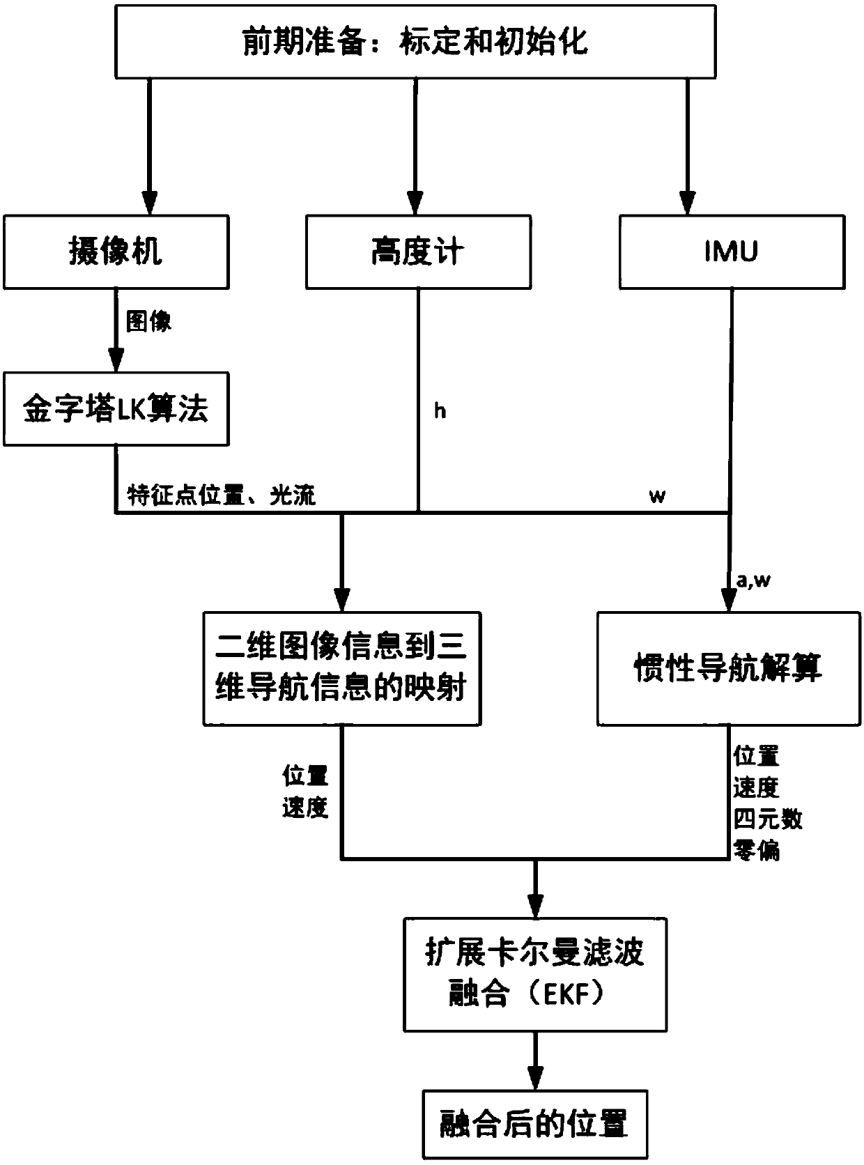
[0021] Specific implementation mode one: the specific process of this embodiment is: a kind of inertial visual integrated navigation method based on optical flow method The specific process is:
[0022] Step 1. Define the world coordinate system O w x w Y w Z w , UAV body coordinate system O b x b Y b Z b , camera coordinate system O c x c Y c Z c , physical imaging coordinate system O 1 xy and pixel image plane coordinate system Ouv;
[0023] Step 2. Three sensors, IMU, camera and altimeter, are mounted on the UAV, and images are collected through the camera, and the collected images are collected according to the following figure 2 The process of pyramid LK solution is used to obtain two-dimensional optical flow data;
[0024] The IMU consists of a gyroscope and an accelerometer;
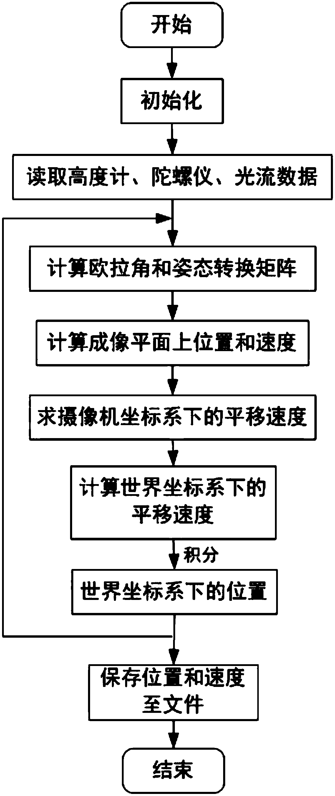
[0025] Step 3. Convert the two-dimensional optical flow data information obtained in step two into three-dimensional navigation information, that is, the position of the drone in the...
specific Embodiment approach 2
[0031] Specific embodiment two: the difference between this embodiment and specific embodiment one is that the world coordinate system O is defined in the step one w x w Y w Z w , UAV body coordinate system O b x b Y b Z b , camera coordinate system O c x c Y c Z c , physical imaging coordinate system O 1 xy and pixel image plane coordinate system Ouv; specifically:
[0032] a. World coordinate system O w x w Y w Z w :
[0033] Use the North-East-Earth coordinate system as the world coordinate system, the origin of the world coordinate system O w is the projection of the initial position of the UAV on the ground, the coordinate axis O w x w Pointing to Earth North, O w Y w Pointing Earth East, O w Z w Perpendicular to the Earth's surface and pointing down; the world coordinate system is a fixed coordinate system;
[0034] b. UAV body coordinate system O b x b Y b Z b :
[0035] The origin of the body coordinate system O b Taken at the center of mas...
specific Embodiment approach 3
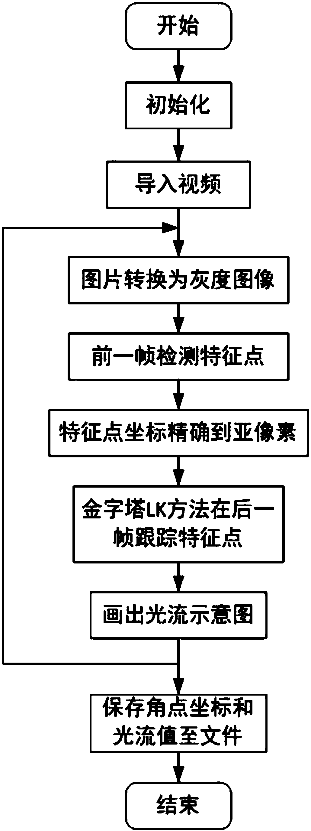
[0043] Specific embodiment three: the difference between this embodiment and specific embodiment one or two is that in the second step, the UAV is equipped with three sensors: IMU, camera and altimeter, and the image is collected by the camera. figure 2 The procedure is to solve the pyramid LK to obtain two-dimensional optical flow data; the specific process is:
[0044] Step 2-1, converting the two frames before and after the color image collected by the camera into a grayscale image;
[0045] Step 2-2, using the Shi-Tomasi corner detection method to find a certain number of feature points in the previous frame, and accurate the coordinates of the feature points in the previous frame to sub-pixel accuracy;
[0046] Step 2-3, adopting the LK algorithm of pyramid thinking to detect the position of the feature point identified in the previous frame in the next frame and determine the coordinates of the feature point in the next frame;
[0047] Step 2-4. Finally, according to th...
PUM
 Abstract
Description
Claims
Application Information