

Air cylinder assembling equipment and assembling method
A technology for assembling equipment and cylinders, applied in metal processing equipment, assembly machines, manufacturing tools, etc., can solve problems such as low production efficiency and low pass rate, and achieve the effects of increasing production capacity, saving labor, and facilitating management
- Summary
- Abstract
- Description
- Claims
- Application Information
AI Technical Summary
Problems solved by technology
Method used
Image

Examples
Embodiment 1
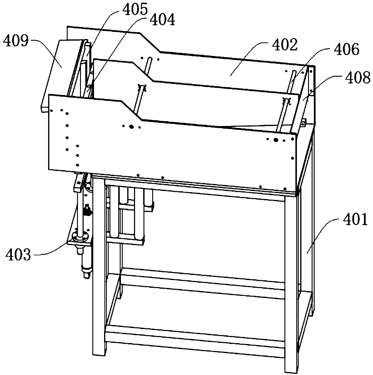
[0059] Such as figure 1 and image 3 As shown, a cylinder inner tube feeding device (or called an inner tube feeder) of this embodiment includes a base 1, a first support frame 401, a first storage box 402, a first cylinder 403, a first upper The push rod 404 , the first push slot 405 , the first limiting rod 406 , the second limiting rod 407 , the first limiting plate 408 , the inclined plate 409 and the first feeding platform 410 .
[0060] The first feeding platform 410 is connected to the base 1, the first support frame 401 is located on one side of the base 1, the first material storage box 402 is installed on the first support frame 401, and the first cylinder 403 is installed on one side of the support frame , located on the lower side of the first material storage box 402, the first cylinder 403 is connected with the first upper push rod 404, the first upper push rod 404 is located inside one side of the material storage box, and the first feeding platform 410 is loca...
Embodiment 2
[0068] On the basis of Embodiment 1, this embodiment provides a cylinder rod core production equipment.
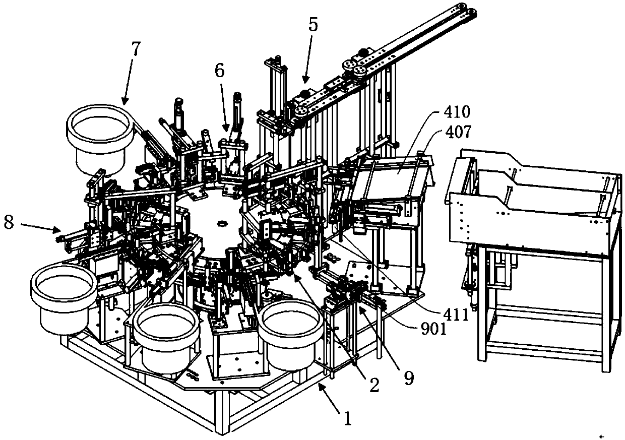
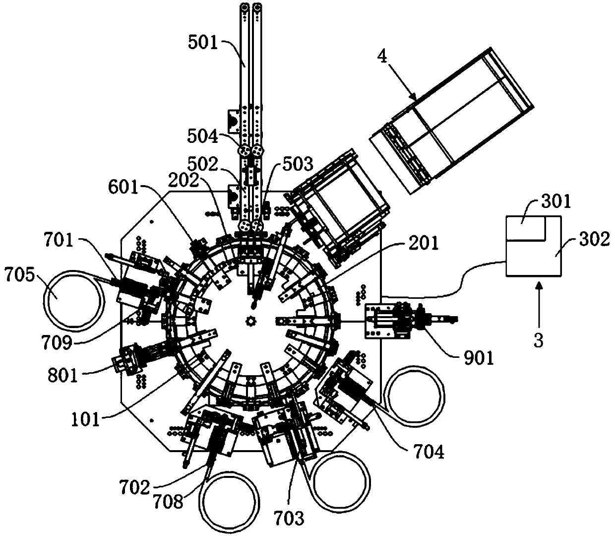
[0069] Such as Figure 1-4 As shown, a cylinder rod core production equipment in this embodiment includes a base 1, a turntable dividing mechanism 2, an electrical control system 3, an inner tube automatic feeding and placement mechanism 4, a piston rod automatic feeding and installation mechanism 5, a pressing Piston rod and refueling mechanism 6, automatic feeding and assembly mechanism 7, turning mechanism 8.
[0070]The base 1 serves as the installation basis of the entire device, providing a support base for all components, and ensuring the continuous and effective work of each component on the base 1 . And the base 1 is provided with a sensor 101 inside each workpiece clamping area along the stationary dividing disk 201. The sensor 101 is used to detect the state of the workpiece clamped by the dividing disk 201, and feed back the detected result information to the ...
Embodiment 3
[0080] This embodiment provides a production method of a cylinder rod core production equipment according to a kind of cylinder rod core production equipment in embodiment 2, comprising the following steps:
[0081] S1. Raw material preparation, put the inner tube into the material storage box of the inner tube automatic feeding and placement mechanism 4, place the piston rod on the first conveyor belt 501 of the piston rod automatic feeding and installation mechanism 5, and place the piston rod to the control box surrounding the base 1 in turn. Valve automatic feeding and assembly mechanism 701, leather bowl automatic feeding and assembly mechanism 702, bowl pad automatic feeding and assembly mechanism 703, and rear top set automatic feeding and assembly mechanism 704. and the rear top cover.
[0082] S2. Turn on the power, the motor starts to rotate, the inner tube automatic feeding and placement mechanism 4 starts feeding, the first cylinder 403 pushes the first upper push ...
PUM
 Abstract
Description
Claims
Application Information