Combined tool for transportation in narrow space and using method thereof

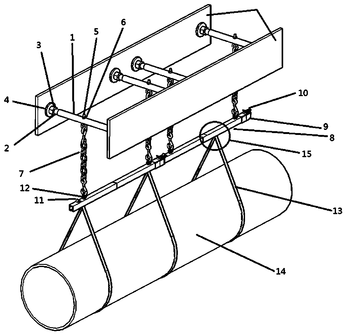
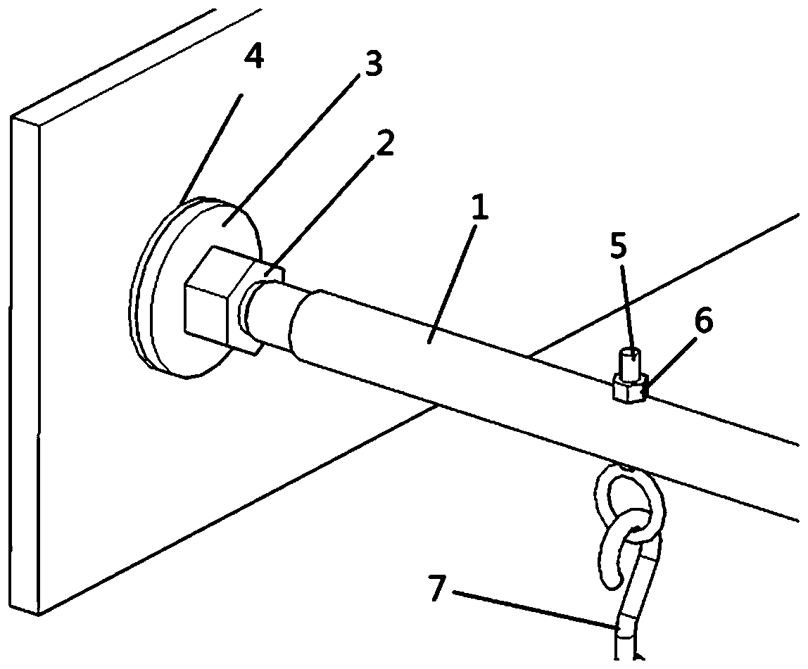
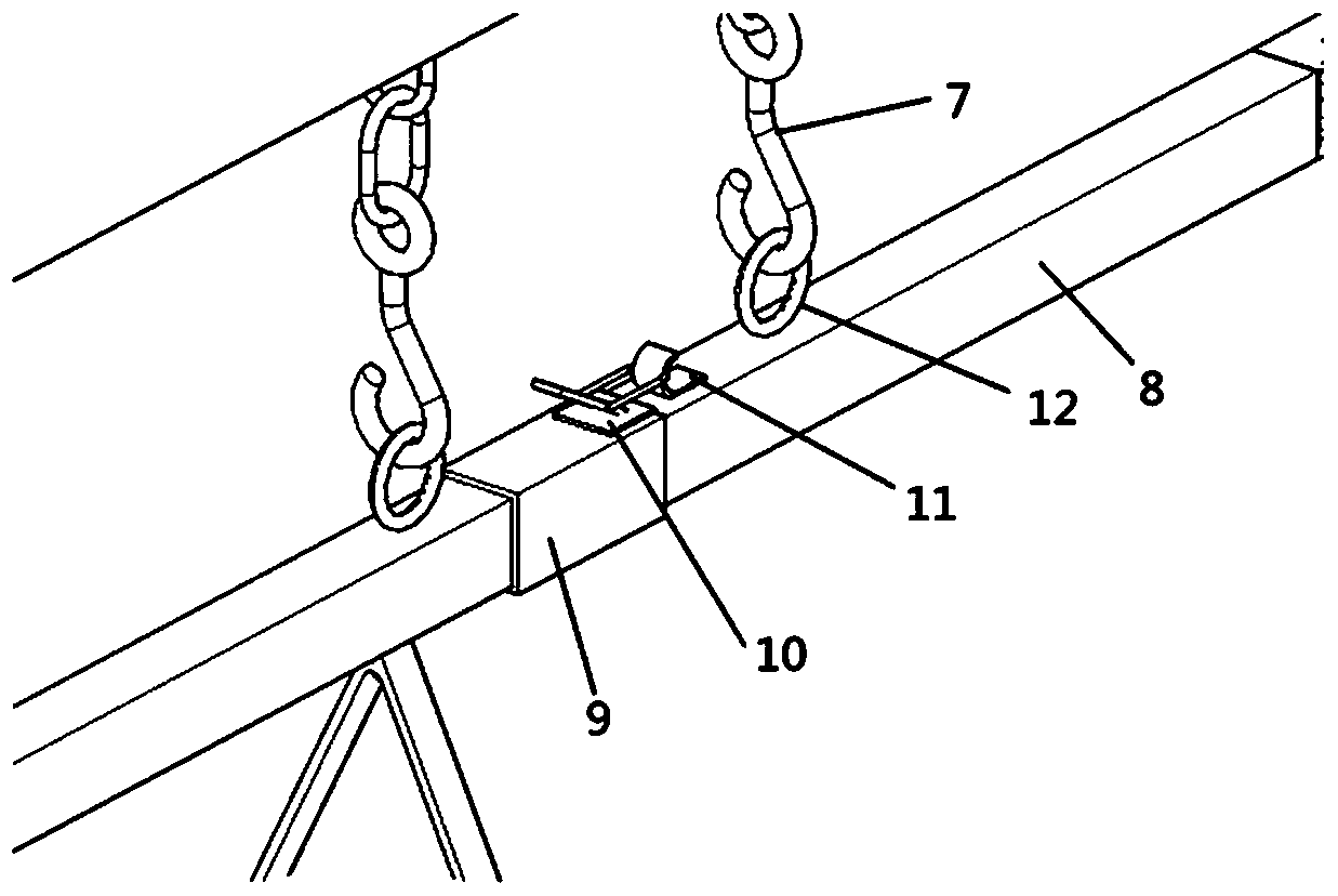
An in-space, combined technology, applied in the field of combined tooling, can solve the problems of outfitting parts, equipment damage, inconvenient operation, time and economic loss, etc., and achieve the effect of reducing labor intensity, convenient disassembly and assembly, and high practical value.

Pending Publication Date: 2019-04-02
SHANGHAI SHIPBUILDING TECH RES INST
0 Cites 0 Cited by

AI-Extracted Technical Summary

Problems solved by technology

Especially for the entry of outfitting and equipment in narrow cabins, because the crane cannot reach them, they are often en...

Method used

During use, the transport piece that needs to be transported is hung below the connectable track assembly by the sling, and the effect of transporting the transport piece along the connectable track assembly is achieved by being arranged on the pulley assembly 15 in the connectable track assembly . Since the two ends of the top support rod are respectively equipped with radial pressurized parts, the top support rod extends along the rod body and is firmly suspended in the narrow space, which is convenient for disassembly and assembly, effectively reduces the labor intensity of the construction personnel on site, and improves the construction efficiency. Efficiency, can be suitable for narrow spaces of various shapes and structures, and has high practical value.
Further, radial pressurization part comprises bolt 2, and the two ends of top support bar are provided with the internal thread that matches with bolt, and the end of bolt is provided with a brace plate 3, and the outside of brace plate is bonded with a piece of rubber pad slice 4. By turning the bolt, the length of the top support rod can be adjusted, so that the top support rod is fixedly connected to the two side walls of the narrow channel through outward radial tension. In order to achieve a better radial pressurization effect, the rubber gasket is in the shape of a concave suction cup, and at the same time, there is a water injection groove on the suction surface of the concave suction cup. The effect is better, ensuring that the top support rod...

Abstract

The invention discloses a combined tool for transportation in a narrow space. The combined tool comprises a top supporting rod assembly and a connecting type rail assembly, wherein the top supportingrod assembly is arranged at the upper part, and the connecting type rail assembly is hung below the top supporting rod assembly; and the top supporting rod assembly comprises a plurality of top supporting rods, wherein the connecting type rail assembly comprises a plurality of rail assemblies which are connected in sequence, and the top supporting rod assembly and the detachable rail assembly arematched, so that the combined tool can extend in the narrow space; radial supercharging parts are arranged at the two ends of the top supporting rods correspondingly, so that the top supporting rods extend along a rod body and are firmly suspended in the narrow space, and the top supporting rod assembly and the connecting type rail assembly are connected through a chain. During use, the top supporting rods are installed according to actual requirements of the construction site, the connecting type rail assembly is used for carrying out rail connection according to the requirements, and then the transport of outfitting parts and equipment and the like are realized through pulley blocks, so that the labor intensity of workers is effectively reduced, the production efficiency is improved, andthe combined tool has high practical value.

Application Domain

Runways

Technology Topic

EngineeringBlock and tackle +1

Image

  • Combined tool for transportation in narrow space and using method thereof
  • Combined tool for transportation in narrow space and using method thereof
  • Combined tool for transportation in narrow space and using method thereof

Examples

  • Experimental program(1)

Example Embodiment

[0024] The technical solutions of the present invention will be clearly and completely described below with reference to the accompanying drawings. Obviously, the described embodiments are a part of the embodiments of the present invention, but not all of the embodiments. Based on the embodiments of the present invention, all other embodiments obtained by those of ordinary skill in the art without creative efforts shall fall within the protection scope of the present invention.
[0025] In the description of the present invention, it should be noted that the terms "installed", "connected" and "connected" should be understood in a broad sense, unless otherwise expressly specified and limited, for example, it may be a fixed connection or a detachable connection Connection, or integral connection; it can be directly connected, or indirectly connected through an intermediate medium, and it can be the internal communication of two elements. For those of ordinary skill in the art, the specific meanings of the above terms in the present invention can be understood in specific situations.
[0026] The present invention provides a combined tooling for transportation in a narrow space, refer to figure 1 The difference from the prior art is that the combined tooling includes an upper top support rod assembly and an attachable track assembly hoisted below the top support rod assembly, and the top support rod assembly includes several top support rods 1, which can be connected The type rail assembly includes several rail assemblies connected in sequence. The top strut assembly cooperates with the connectable rail assembly so that the combined tooling can be extended infinitely in a narrow space, and the size of this extension is determined according to the transportation items that need to be transported; The two ends of the top support rod are respectively provided with radial pressurizers, so that the top support rod is axially elongated along the rod body and is firmly suspended in the narrow space, and the chain 7 is passed between the top support rod assembly and the connectable track assembly. connected. There are generally 5-50 top support rods and connectable rails described here.
[0027] When in use, the transport piece to be transported is hung under the connectable track assembly through a sling, and the pulley assembly 15 provided in the connectable track assembly is used to transport the transport piece along the connectable track assembly. Since the two ends of the top support rod are respectively provided with radial pressurizing parts, the top support rod is extended along the rod body and is firmly suspended in the narrow space, which is convenient for disassembly and assembly, effectively reduces the labor intensity of on-site construction personnel, and improves the construction efficiency. Efficiency, it can be suitable for narrow spaces of various shapes and structures, and has high practical value.
[0028] In one embodiment, the connectable track assembly includes several track assemblies connected in sequence, and the top strut assembly cooperates with the connectable track assembly so that the combined tooling can be infinitely extended in a narrow space. Each track assembly includes a section of an attachable track 8, one end of the attachable track is sleeved with a track sleeve 9, and the upper surface of the other end is provided with a fixing hasp 11 to fix the track sleeve and the attachable track For connection, a hoisting ring 12 is arranged above the connectable track, the hoisting ring is used to connect with the chain, a pulley assembly is placed in the connectable track, and a sling 13 is suspended below the pulley assembly, and the sling is used for hoisting in a narrow space items that need to be transported.
[0029] Specifically, the length of the track sleeve accounts for 1/4--1/6 of the length of the connectable track, one end of the connectable track is inserted into the track sleeve, and a stop baffle is arranged in the center of the track sleeve, so that the One end of the connectable track can only be inserted into the half position of the track sleeve. At the same time, the outside of the track sleeve is provided with a locking member 10 to be matched with the fixed hasp, so that the two adjacent connectable tracks can pass through the track sleeve. Fixed connection. Further, the track sleeve here is a gradual structure with a slightly larger diameter at both ends and a slightly smaller diameter in the middle, which ensures the firmness of the connectable track after insertion, and will not fall off when it is stressed, ensuring the safety of use. sex. At the same time, the middle of the top support rod is provided with a through hole, the hook 5 passes through the through hole and is fixed with a nut 6, a chain 7 is hung below the hook, and the top support rod and the track assembly are connected by a chain.
[0030] Further, the radial pressure booster includes bolts 2, the two ends of the top support rod are provided with internal threads matching the bolts, the ends of the bolts are provided with a support plate 3, and a rubber gasket 4 is bonded to the outside of the support plate. By turning the bolt, the length of the top support rod can be adjusted, so that the top support rod can be fixedly connected with the two side walls of the narrow passage through outward radial tension. In order to achieve a better radial pressurization effect, the rubber gasket is in the shape of a concave suction cup, and there is a water injection groove on the suction cup surface of the concave suction cup. When in use, water can be injected into the water injection groove now, which can make adsorption The effect is better, to ensure that the top support rod will not fall off during the transportation of objects.
[0031] Alternatively, an air-extraction pressing member is arranged on the support plate, and one end of the air-extracting pressing member is communicated with the inner side wall of the rubber gasket. When the rubber gasket is attached to the side wall of the narrow space, it is It can vacuum between the rubber gasket and the side wall of the narrow space, further expand the radial pressure, not only safe and reliable operation, but also further improve the pressure bearing range of the connectable track assembly, which can be transported in a narrow space Heavy parts.
[0032]In a specific embodiment, the combined tooling of the present invention consists of three parts, which are a top strut assembly, an attachable track assembly hoisted below the top strut assembly, and a chain for connecting the two. The top support rod is a thick-walled steel pipe with a certain length, and both ends are drilled with internal threads.
[0033] Specifically, bolts are screwed at both ends of the top support rod, the bolts are made of steel, and their threads match the internal threads at both ends of the top support rod. A circular support plate is welded at the hexagonal end of the bolt to increase the The contact area with the side wall of the narrow space, and a rubber pad of the same size is pasted on the circular support plate to increase the friction coefficient, thereby increasing the static friction.
[0034] A pair of perforations are drilled in the middle of the top support rod, and a hook is inserted into the pair of perforations, the hook is made of steel, and the straight section of the hook has an external thread, which is fixed in the middle of the top support rod by a nut.
[0035] The connectable track is a hanging track, which is made of aluminum-magnesium alloy. Insert one end into the half position of the track sleeve and fix it by welding. The material of the track sleeve is aluminum-magnesium alloy, and its structure is the same as that of the connectable track, but the size is slightly larger than that of the connectable track, so that the connectable track can be inserted into the track sleeve for fixing.
[0036] A locking piece is welded on the upper surface of the track sleeve, and a male hasp is welded on the other end of the connectable track for fixed connection of two adjacent connectable tracks.
[0037] When in use, determine the number of struts required per unit length according to the weight of the outfitting/equipment to be transported, support the top struts on the bulkheads on both sides of the narrow space, and use a wrench to turn the hexagon head of the bolt to make the top struts The rods are elongated to increase radial pressure on the bulkhead, which increases friction and ensures that the top struts do not suddenly slip off during use. Use a chain to connect the hook on the top strut and the sling on the attachable track, hang the attachable track under the top strut, and lengthen the track according to the actual situation of the construction site, and fix it with the hasp locking piece , to ensure that there is no looseness between the accessible rails. Put the pulley block into the track, hoist the outfitting part/equipment through the hook under the pulley block, and realize the movement of the outfitting part/equipment by moving the pulley block in the track.
[0038] In an embodiment of the method of use, the following steps are included: a. According to the length and weight of the required transport piece, determine the number of top support rods and connectable rails required per unit length, and support the top support rod on two sides of the narrow space. On the side bulkhead and fixed; b. The connectable track is hoisted under the top support rod through the chain, and the adjacent connectable tracks are connected by the track sleeve to form the connectable track assembly; c. Put the pulley assembly on the Into the connectable track assembly, a sling is suspended below the pulley assembly, the parts to be transported are hoisted by the sling, and the pulley assembly moves in the track to realize the transportation movement of the transportation parts in a narrow space.
[0039] Preferably, in step a, two ends of the top support rod are respectively provided with radial boosters, so that the top support rod is elongated along the rod body and is firmly suspended in the narrow space, the radial booster includes bolts, and the top support Both ends of the rod are provided with internal threads matched with the bolts, the ends of the bolts are provided with a support plate, and a rubber gasket is bonded to the outside of the support plate.
[0040] Further, in step b, one end of the connectable track is sleeved with a track sleeve, and the upper surface of the other end is provided with a fixed hasp to securely connect the track sleeve and the connectable track, and the connectable track is placed inside the track. There is a pulley assembly, a sling is suspended below the pulley assembly, and the sling is used to hoist objects that need to be transported in a narrow space.
[0041] Further, in step a, a through hole is provided in the middle of the top support rod, the hook passes through the through hole and is fixed with a nut, a chain is hung below the hook, and the top support rod and the track assembly are connected by a chain.
[0042] When in use, the present invention increases the radial pressure by twisting the bolts at both ends of the top strut, thereby increasing the vertical frictional force, and firmly fixing the top strut on the bulkheads/members on both sides of the narrow space, and then The accessible track is suspended by a chain under the top support rod, and the track is lengthened according to the actual needs of the site, so as to realize the transportation of outfitting parts and equipment in a narrow space. The invention has simple structure, convenient disassembly and assembly, avoids manual handling of outfitting parts and equipment, effectively reduces the labor intensity of on-site construction personnel, improves construction efficiency, and has high practical value.
[0043] The specific embodiments of the present invention have been described above in detail, but they are only used as examples, and the present invention is not limited to the specific embodiments described above. For those skilled in the art, any equivalent modifications and substitutions to the present invention are also within the scope of the present invention. Therefore, equivalent changes and modifications made without departing from the spirit and scope of the present invention should be included within the scope of the present invention.

PUM

no PUM

Description & Claims & Application Information

We can also present the details of the Description, Claims and Application information to help users get a comprehensive understanding of the technical details of the patent, such as background art, summary of invention, brief description of drawings, description of embodiments, and other original content. On the other hand, users can also determine the specific scope of protection of the technology through the list of claims; as well as understand the changes in the life cycle of the technology with the presentation of the patent timeline. Login to view more.

Similar technology patents

Antenna panel assembling structure

Owner:NO 54 INST OF CHINA ELECTRONICS SCI & TECH GRP

Net cage model test platform

InactiveCN105300678AEasy to assemble and disassembleReduce the impact of errors
Owner:EAST CHINA SEA FISHERIES RES INST CHINESE ACAD OF FISHERY SCI

Assembly type precast concrete member die

Owner:界首市宝业瑞祥建筑工业化有限公司

Combined reflector and illuminating lamp thereof

Owner:OCEANS KING LIGHTING SCI&TECH CO LTD +1

Classification and recommendation of technical efficacy words

  • Easy to assemble and disassemble
  • Reduce labor intensity

Method for intelligent automatic identification of transmission circuit parts

Owner:INFORMATION COMM COMPANY STATE GRID SHANDONG ELECTRIC POWER +2

City regional railway signal system and control method thereof

Owner:CHINA RAILWAY SIYUAN SURVEY & DESIGN GRP

Railway bearing intelligent on-line detection method and its device

InactiveCN101290265AReduce labor intensity
Owner:洛阳铭昊测控科技有限公司
Why Eureka
Try Eureka