Floating electrical connector

An electrical connector, floating sleeve technology, applied in the direction of connection, two-part connection device, parts of the connection device, etc., can solve the problem of increasing product size and production cost, unable to achieve 360° force, high processing surface requirements, etc. problems, to achieve the effect of compact structure, meeting watertight requirements, and small volume

Active Publication Date: 2019-04-02
杭州航天电子技术有限公司
View PDF5 Cites 3 Cited by
  • Summary
  • Abstract
  • Description
  • Claims
  • Application Information

AI Technical Summary

Problems solved by technology

[0004] However, there are many problems in the existing floating electrical connectors: the axial angle deviation between the plug and the socket can only be aligned by the keyway at the mating end, and it is impossible to achieve 360° force, and there are many structural parts, which makes assembly difficult. The requirements for the processed surface are higher, which increases the overall size and production cost of the product

Method used


Image

  • Floating electrical connector
  • Floating electrical connector
  • Floating electrical connector

Examples


Embodiment 1

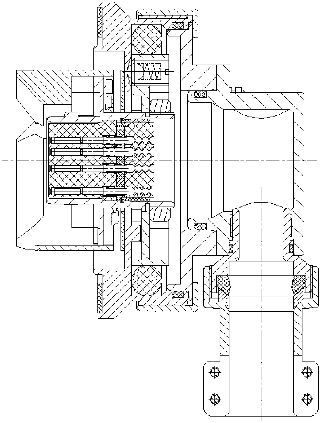
[0044] In this embodiment, the floating electrical connector may specifically include: a plug and a socket. Wherein, the plug includes: floating sleeve 2 and plug housing 3 ; the socket includes: roller 31 and socket housing 33 .

[0045]The floating sleeve 2 is rigidly fixed to the plug housing 3, and the roller 31 is rigidly connected to the socket housing 33 by riveting; the floating sleeve 2 is provided with guide chamfers and notch chamfers, when the plug is mated with the socket, the floating sleeve 2 The guide chamfers of the socket contact with the socket and advance gradually. The guide chamfers make the plug move axially and radially along the socket to adjust the position and achieve the purpose of alignment; during the mating process of the plug and the socket, the rollers of the socket and the floating The chamfering of the notch on the sleeve 2 contacts, and the floating sleeve 2 drives the plug housing to rotate along the socket to achieve the mating rough guide...

Embodiment 2

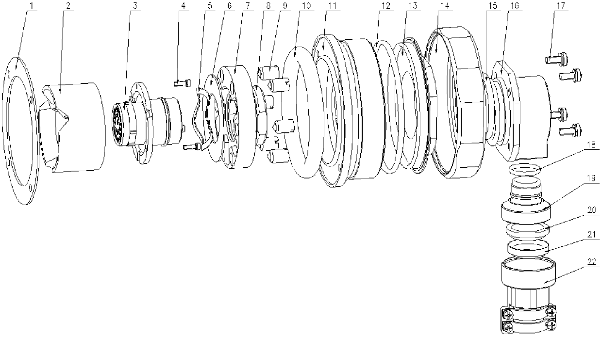
[0047] Such as Figure 2-6 , The plug can also include: a wave reed 5, a ball plunger 9, a rubber piece 10, a plug housing fixing frame 7, a tightening ring 8 and a plug cable cover fixing frame 11.

[0048] The wave reed 5 is arranged between the plug housing 3 and the plug housing fixing bracket 7; the ball plunger 9 is assembled on the plug housing fixing bracket 7 through screw fit; the plug housing fixing bracket 7 is connected with the plug housing 3 The rib groove structure between them is positioned, and is rigidly fixed on the plug housing 3 through the tightening ring 8; the plug cable cover fixing frame 11 is assembled between the wave reed 5 and the plug housing fixing frame 7, and the plug cable cover fixing frame 11 The fixed frame 7 of the plug housing is limited by the groove structure, and the fixed frame 11 of the plug cable cover is provided with a pit structure uniformly distributed on the circumference; the rubber part 10 is assembled under the fixed frame...

Embodiment 3

[0054] Such as Figure 7-9 , The socket may also include: a socket cable cover 35, a screw III 36, a socket tail cover connecting ring 38 and a socket tail cover 311. The socket cable cover body 35 is assembled with the socket housing 33 through screw III 36; the socket tail cover connecting ring 38 is assembled with the socket cable cover body 35 through threaded connection; the socket tail cover connecting ring 38 and the socket tail cover 311 are threaded.

[0055] Preferably, the socket may further include: O-ring IV 32 , O-ring V 34 , O-ring VI 37 , socket waterproof sealing ring 39 and socket pressure sleeve 310 . O-ring IV 32 is set at the front end of socket housing 33; O-ring V 34 is radially sealed between socket cable cover 35 and socket housing 33; O-ring is used between socket cable cover 35 and socket tail cover connecting ring 38 Ring Ⅴ 37 is radially sealed; the socket tail cover connecting ring 38 and the socket tail cover 311 are equipped with a socket water...


PUM


Abstract

The invention discloses a floating electrical connector, comprising: a plug and a socket; the plug comprises: a floating sleeve and a plug housing; the socket comprises: a roller and a socket housing;the floating sleeve is rigidly fixed with the plug housing, and the roller is rigidly connected with the socket housing by riveting; the floating sleeve is provided with a guiding chamfer and a notchchamfer; the front end of the plug housing is provided with a guiding key, and the front end of the socket housing is provided with a corresponding key slot. The floating electrical connector realizes a three-dimensional six-degree-of-freedom floating function of mechanically docking the electrical connector, has a centering reset function in an unplugged state, and has the advantages of compactstructure and small size.

Description

technical field [0001] The invention belongs to the technical field of electrical connectors, in particular to a floating electrical connector. Background technique [0002] Generally, an electrical connector is mainly composed of two parts, a plug and a socket. When the electrical connector is in use, the plug and the socket are mated to realize the transmission of electrical signals. With the improvement of computer technology and mechanical automation level, more and more electrical connectors in the electrical transmission docking system are automatically docked mechanically. Mechanical docking is widely used in special environments where manual docking is relatively difficult, such as deep-water exploration, space, high-temperature radiation, and radioactivity; at the same time, today, when computer program control is used more and more, the entire process can be automated through mechanical docking. operate. [0003] Compared with manual operation, the flexibility a...

Claims


Application Information

Patent Timeline
Patent Type & Authority Applications(China)
IPC IPC(8): H01R13/631H01R13/502H01R13/52H01R24/00
CPCH01R13/502H01R13/5202H01R13/5205H01R13/631H01R13/6315H01R24/00
Inventor 邵海丰郑志超谭朝华沈龙蔡海燕
Owner 杭州航天电子技术有限公司
Why Eureka
Try Eureka