Automatic glue charging system and automatic glue dipping equipment

An automatic, dipping technology, applied in the direction of coating, surface coating liquid devices, etc., can solve the problems of large fluctuations in the liquid level of the production glue tank, affect production efficiency, increase the failure rate, etc., and achieve stable dipping liquid level , high production efficiency and low bubble generation rate

Inactive Publication Date: 2019-04-05
SHANDONG XINGYU GLOVES
View PDF5 Cites 1 Cited by
  • Summary
  • Abstract
  • Description
  • Claims
  • Application Information

AI Technical Summary

Problems solved by technology

Long-fiber raw materials need to follow the trend in the process of stirring and transportation, so that the microstructure will be neat and the macrostructure will be uniform, while the staggered stirring will make the structure staggered and poor stability
The impulsive force of the rubber delivery pump makes the liquid level of the production glue tank fluctuate greatly
In addition, the rubber in the rubber material is likely to cause blockage of the rubber pump, resulting in an increase in the failure rate, requiring shutdown and cleaning, and affecting production efficiency

Method used


Image

  • Automatic glue charging system and automatic glue dipping equipment

Examples


Embodiment 1

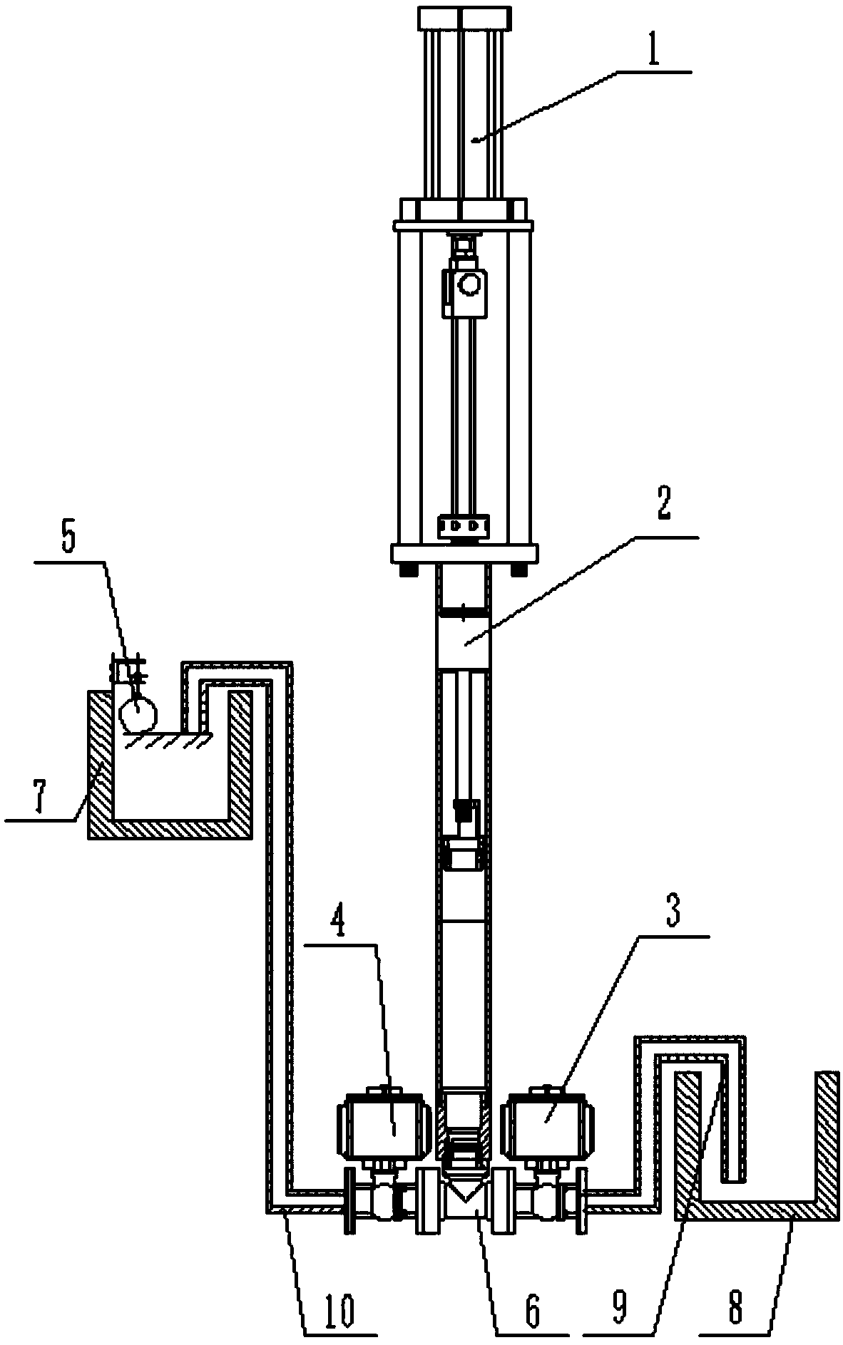
[0034] Such as figure 1 As shown, the automatic glue adding system includes a suction pipe 9, a pressure pipe 10, a first valve 3, a second valve 4, and a vacuum system 2. The vacuum system 2 includes a vertical cylindrical inner cavity, and the piston fits into the inner cavity. The side wall reciprocates up and down along the inner cavity to adjust the volume of the inner cavity. The piston is driven by the power unit 1, which can be directly pushed and pulled, or can be driven by a screw thread, which is more stable and powerful.

[0035] Other methods can also be used, such as a fan-shaped inner cavity, and then the volume of the inner cavity can be adjusted by rotating a pressing plate with a radius length along the center of the circle.

[0036] The lower part of the inner cavity can be connected with a tee 6 , the tee 6 communicates with the suction pipe 9 through the first valve 3 , and the tee 6 also communicates with the pressure pipe 10 through the second valve 4 ....

Embodiment 2

[0047] As in Embodiment 1, a transparent observation window is provided on the cavity side wall of the vacuum system 2 . When there is a problem in the inner cavity, the second valve 4 is closed, the first valve 3 is opened, the piston is pressed to the lowest level, and the rubber material flows back to the discharge tank 8 or a separate recovery tank.

Embodiment 3

[0049] As in Example 1, the first valve 3 and the second valve 4 are one-way valves, the flow direction of the first valve 3 is that the suction pipe 9 flows to the inner cavity, and the flow direction of the second valve 4 is that the inner cavity flows to the pressure tube 10 .

[0050] Like this, as long as the volume of the inner cavity becomes smaller, the sizing material in the inner cavity will be squeezed to the pressure material tube 10 . As long as the volume of the inner cavity becomes larger, the glue material of the suction pipe 9 is sucked into the inner cavity. Simple and convenient, reducing the complexity of the control system.


PUM


Abstract

The invention relates to an automatic glue charging system. The automatic glue charging system comprises a material absorption tube, a material pressing tube and a vacuum system; the vacuum system comprises an inner cavity with changing volume under control, the material absorption tube communicates with the inner cavity through a first valve, and the inner cavity communicates with the material pressing tube through a second valve. According to the automatic glue charging system, glue materials can be automatically added, the stability of the glue materials is good, the liquid level of glue dipping is stable, the generation probability of bubbles is reduced, faults cannot be generated due to rubber, the fault rate is low, and the production efficiency is high; and labor cost is saved, thestructure is simple, manufacturing is convenient, and maintenance is facilitated.

Description

technical field [0001] The invention relates to the field of dipping production, in particular to an automatic glue adding system. [0002] The invention also relates to an automatic dipping equipment. Background technique [0003] At present, during the production of dipped gloves, the rubber is added manually or by a rubber pump. [0004] Manual operation is slow. With the continuous improvement of production efficiency, the frequency of glue addition and the amount of glue used also increase, which increases the labor intensity of the operator and virtually increases the labor cost; when manually adding glue, it may be due to improper operation. Bubbles are generated in the glue pool, which will affect the appearance quality of the gloves; [0005] Existing rubber pumps basically use blades, threaded rods and other structures to transport rubber materials by means of rotation and centrifugation. The high shear force has a great impact on the stability of the rubber mate...

Claims


Application Information

Patent Timeline
Patent Type & Authority Applications(China)
IPC IPC(8): B05C3/02B05C11/10B05C11/11
CPCB05C3/02B05C11/101B05C11/1013B05C11/11
Inventor 周星余周海涛
Owner SHANDONG XINGYU GLOVES
Why Eureka
Try Eureka