Working method for conveying sorting device

A sorting device and working method technology, applied in chemical instruments and methods, grading, solid separation, etc., can solve the problems of waste materials, leakage and scattering of materials, large volume and weight of unloading bins, etc., to improve operation speed and efficiency. , the effect of increasing the sorting space and reducing the sorting time

Pending Publication Date: 2019-04-05
CHANGSHA UNIVERSITY OF SCIENCE AND TECHNOLOGY
View PDF3 Cites 1 Cited by
  • Summary
  • Abstract
  • Description
  • Claims
  • Application Information

AI Technical Summary

Problems solved by technology

[0004] 1. In the transportation of the prior art, due to the single path transportation, the transportation efficiency is low, and the unloading operation at the downstream end is single
[0005] 2. The sorting device of the prior art often needs to stop the materials in situ for sorting, and the accumulation of a small amount of materials will result in a serious waste of time and extremely low efficiency.
[0006] 3. In the prior art, there is a technical solution for improving work efficiency by dispersing the material, but it is difficult to provide more sorting paths in one sorting position due to the crowded site in a single position
[0007] 4. The material feeding method in the prior art is single, and only multi-stage feeding valves are used for sorting and distributing. The sorting method has limitations, and it is difficult to adapt to the requirements of multiple working conditions.
[0008] 5. In the sorting device of the prior art, there is a technology of moving the lower hopper at the downstream end to switch the conveying path, such as switching the conversion path back and forth between the four lower hoppers, but due to the large volume and weight of the lower hopper, the increase In order to increase the difficulty of completion, greater kinetic energy is required to drive, which increases the cost of work
[0009] 6. In the existing technology, when switching between different conveying levels, it often causes material leakage and scattering, wastes materials, and causes environmental pollution

Method used


Image

  • Working method for conveying sorting device
  • Working method for conveying sorting device
  • Working method for conveying sorting device

Examples


Embodiment Construction

[0039] The present invention will be further described below in conjunction with the accompanying drawings and embodiments.

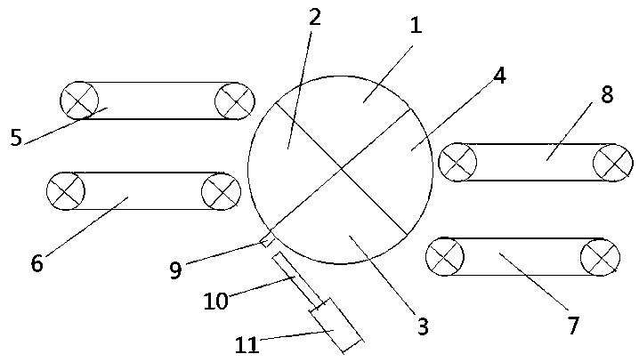
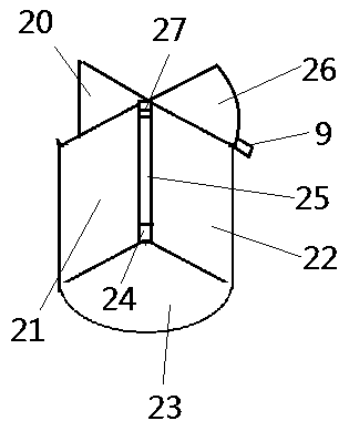
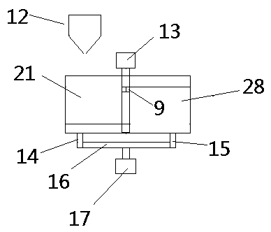
[0040] As shown in the figure: a working method of a conveying and sorting device, the conveying and sorting device includes a first sorting area, a second sorting area, a third sorting area, a fourth sorting area, a first conveyor belt, a second conveyor belt, The third conveyor belt, the fourth conveyor belt, the support rod, the piston rod, the cylinder, the feeding valve, the main motor, the first pillar, the second pillar, the support connecting frame, the auxiliary motor, the ball head, the protective pad, and the connecting baffle , connection baffle plate two, connection baffle plate three, connection baffle plate four, lower sorting plate one, lower sorting plate two, upper sorting plate, lower connecting ring, main shaft, upper connecting ring; described working method includes the first Sorting area selection method, second sorting area selec...


PUM


Abstract

The invention provides a working method for conveying a sorting device. The sorting method comprises a first sorting region sorting method, a second sorting region sorting method, a third sorting region sorting method and a fourth sorting region sorting method. The second sorting region sorting method comprises a receiving method and an unloading method, wherein the receiving method comprises thestep that a material falls on a lower sorting plate I when the lower sorting plate I in a second sorting region rotates to a position below a discharging valve; and the unloading method comprises thefollowing steps that the lower sorting plate I is driven to rotate clockwise by an auxiliary motor when a third sorting region rotates to a position below the discharging valve, a connecting baffle isused for baffling the material on the lower sorting plate I to make the material fall on a fourth conveying belt, and the material is conveyed downstream; and afterwards the auxiliary motor is used for driving the lower sorting plate I to rotate anticlockwise so as to rotate and returns to the original position in a light loading manner in a direction opposite to the rotation direction of a sorting platform.

Description

technical field [0001] The invention relates to the fields related to conveyors and bulk material transportation, in particular to a working method of a conveying and sorting device. Background technique [0002] With the development of science and technology and economic development, the transportation of materials is becoming more and more frequent. At present, the transportation of existing bulk materials such as coal, iron ore, grain, gravel, etc. is generally realized by conveying machinery. These conveying machines transport materials to their destinations to achieve normal industrial production. In the process of material transportation, in many cases, it is necessary to transfer materials from one conveying device to another, such as transferring from an upper-level conveyor belt to a lower-level conveyor belt, the commonly used transfer device can use a discharge funnel. [0003] In actual use, there are the following problems: [0004] 1. In the transportation o...

Claims


Application Information

Patent Timeline
Patent Type & Authority Applications(China)
IPC IPC(8): B07B13/16B07B13/05
CPCB07B13/05B07B13/16
Inventor 曹瑛王金行尹来容刘川川李方义
Owner CHANGSHA UNIVERSITY OF SCIENCE AND TECHNOLOGY
Why Eureka
Try Eureka