
Electrolytic deburring device of air cylinder body

A technology for deburring and cylinder block, applied in the field of electrolytic deburring device for cylinder block, can solve the problems of weakened electrode rod strength, unusable use, low production efficiency, etc., and achieves the effect of compact structure, ideal effect and high work efficiency

Active Publication Date: 2019-04-05
GUANGXI YUCHAI MASCH CO LTD
View PDF16 Cites 2 Cited by
  • Summary
  • Abstract
  • Description
  • Claims
  • Application Information

AI Technical Summary

Problems solved by technology

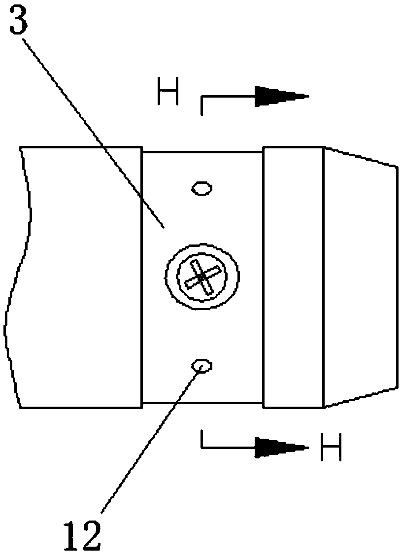
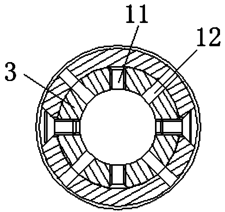
[0003] like figure 1 and 2 As shown, in the existing deburring device, the electrode rod used in it is installed on the same circumference of the electrolytic coil position, not only is provided with 4 threaded holes, but also is provided with 4 spray holes at the same time, so that the electrode rod The strength of the circumferential position of the hole is greatly weakened, and it is easy to break during the working process and cannot be used anymore
In addition, the left electrode rod, the right electrode rod and the auxiliary oil passage electrode rod of the main oil passage need to be connected with three electrolyte delivery hoses. In this way, for the same electrolytic deburring machine to be compatible with various workpieces for electrolytic processing, it is difficult to convert different The electrode rod needs to be replaced when the cylinder block of the model is used. Every time the electrode rod is replaced, three electrolyte delivery hoses need to be disassembled, which is inconvenient to operate and low in production efficiency.

Method used


Image

  • Electrolytic deburring device of air cylinder body
  • Electrolytic deburring device of air cylinder body
  • Electrolytic deburring device of air cylinder body

Examples


Embodiment Construction

[0035] The present invention will be further described below in conjunction with the specific embodiments in the accompanying drawings.

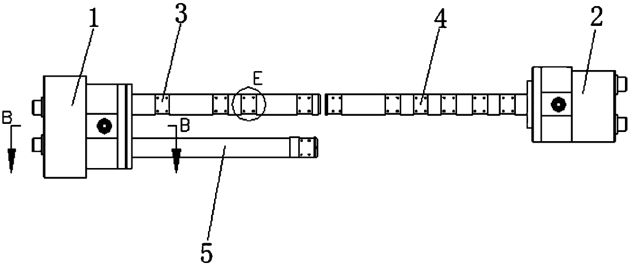
[0036] refer to Figure 3-13 As shown, a cylinder block electrolytic deburring device of the present invention includes an electrode left joint 1, an electrode right joint 2, a main oil passage left electrode 3, a main oil passage right electrode 4 and an auxiliary oil passage electrode 5, wherein the electrode left The joint 1 includes a panel 6 and a socket 7. The left electrode 3 of the main oil gallery and the electrode 5 of the auxiliary oil gallery are integrally installed on one side of the panel 6 through the socket 7. The panel 6 is provided with a first infusion hole 8, which The first infusion hole 8 is provided along the radial direction of the panel 6 and communicates with the outside world. The opening end of the infusion hole is provided with threads for easy connection of the electrolyte infusion hose. The hole 8 is connecte...


PUM


Abstract

The invention discloses an electrolytic deburring device of air cylinder body. The electrolytic deburring device of air cylinder body comprises an electrode left connector, an electrode right connector, a main oil channel left electrode, a main oil channel right electrode and an auxiliary oil channel electrode, wherein the electrode left connector comprises a panel and a connecting sleeve, the main oil channel left electrode and the auxiliary oil channel electrode are integrally installed on one side of the panel through the connecting sleeve, a first infusion hole is formed in the panel, andthe two third infusion holes communicating the first infusion hole with second infusion holes formed in the main oil channel left electrode and the auxiliary oil channel electrode correspondingly is further formed in one side of the panel; and threaded holes and liquid spraying holes are both formed in the main oil channel left electrode, the main oil channel right electrode and the auxiliary oilchannel electrode, the threaded holes and the liquid spraying holes are arranged at intervals along the axial direction of the corresponding electrodes. According to the electrolytic deburring deviceof the air cylinder body, the strength of an electrode rod can be effectively improved, the service life of the electrode rod can be prolonged, so that the electrolyte is more sufficiently and uniformly distributed around the burrs, and the effect of electrolytic deburring is improved.

Description

technical field [0001] The present invention relates to a deburring device, more specifically, it relates to an electrolytic deburring device for a cylinder block. Background technique [0002] During the manufacturing process of the engine cylinder block, burrs will be generated at the intersection of the main oil passage, auxiliary oil passage and the horizontal crankshaft lubricating oil hole, piston lubricating oil hole, rocker shaft lubricating oil hole, etc., and it is necessary to try to remove the burrs. Inside the cavity of the cylinder block, it is not easy to be found and cleaned. If it is not cleaned, it will directly affect the running performance of the engine, and even cause the failure of burning the bearing bush. Among the existing deburring methods, steel wire brushes and abrasive brushes are used for manual deburring, and electrolytic deburring is also used. The effect of manual deburring is not good, while the effect of electrolytic deburring is better. ...

Claims


Application Information

Patent Timeline
Patent Type & Authority Applications(China)
IPC IPC(8): B23H9/02B23H11/00
CPCB23H9/02B23H11/00Y02P70/10
Inventor 冯文源冯炜
Owner GUANGXI YUCHAI MASCH CO LTD
Learn More