

Polygonal multi-welding-surface ultrasonic metal tool head
A metal tool and polygon technology, which is applied in the field of polygonal multi-welding surface ultrasonic metal tool heads, can solve the problems of low usage rate, less welding surface, short service life, etc., so as to improve work efficiency, reduce replacement work, and prolong service life. Effect
- Summary
- Abstract
- Description
- Claims
- Application Information
AI Technical Summary
Problems solved by technology
Method used
Image

Examples
Embodiment 2
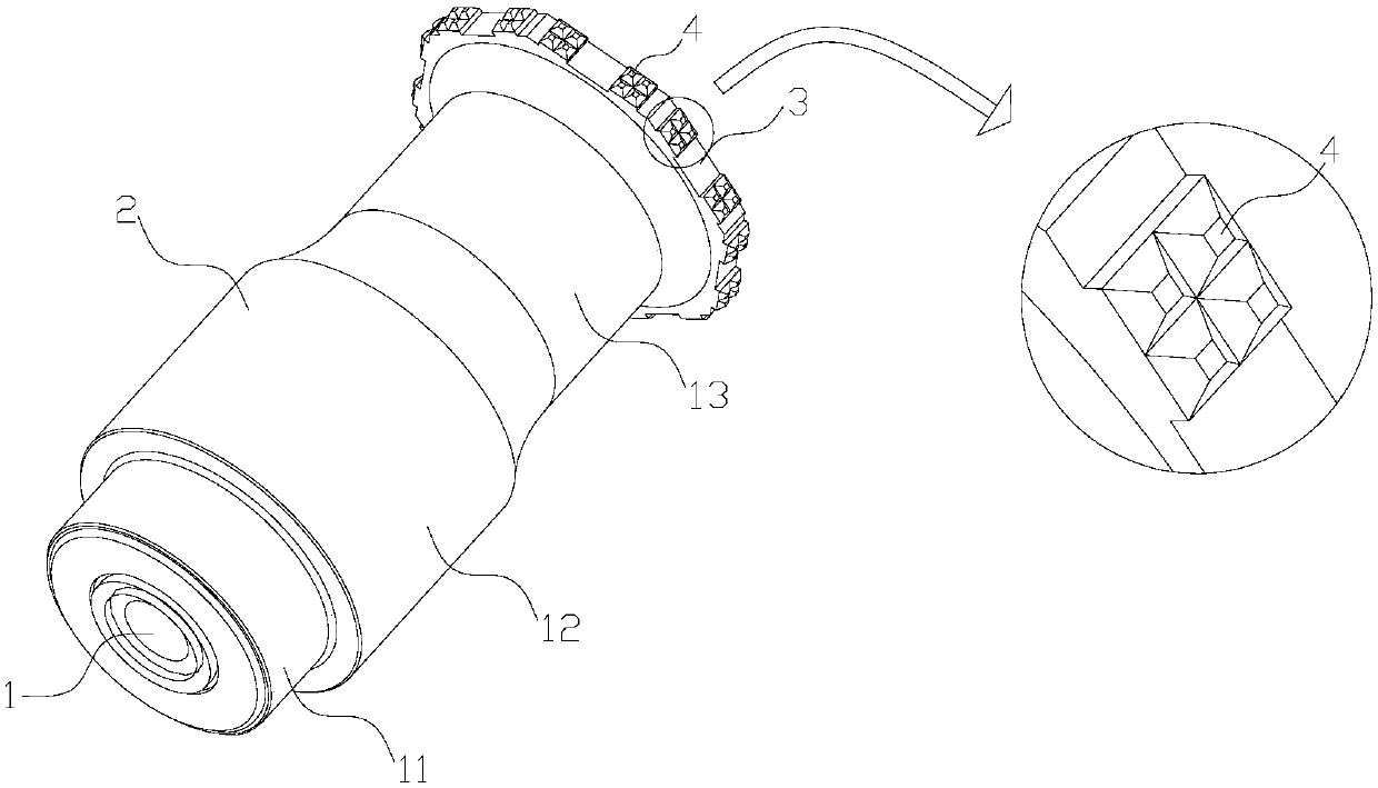
[0044] Such as Figure 4 As shown, it is a polygonal multi-welding surface ultrasonic metal tool head. The polygonal multi-welding surface ultrasonic metal tool head includes a welding head body 1, a connecting hole 2, a welding end 3 and a welding tooth 4, the connecting holes 2 are arranged in pairs at both ends of the welding head body 1, and the welding end 3 is arranged on the welding head body 1, the welding end 3 is arranged around the welding head body 1 and protrudes from the welding head body 1, and the welding teeth 4 are arranged on the side of the welding end 3. The length of the horn body 1 is a half wavelength, and in other embodiments, the length of the horn body 1 can also be a full wavelength. The cross-section of the welding end 3 is a regular pentagon. In other embodiments, the cross-section of the welding end 3 can also be a regular hexagon, a regular octagon, a regular decagon, or a regular dodecagon.
[0045] As a preferred embodiment, the welding head...
Embodiment 3
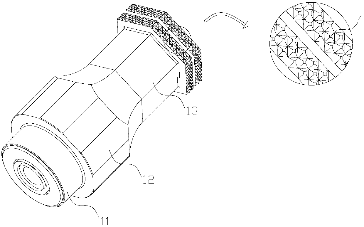
[0049] Such as Figure 5 As shown, the difference between embodiment 3 and embodiment 2 is: the cross section of the transmission rod 13 is a regular hexagon, the welding end 3 is a cylinder with a cross section of a regular hexagon, and each side of the transmission rod 13 is in contact with the The sides of the welding end 3 are parallel.
[0050] As a preferred embodiment, the side of the welding end 3 is covered with welding teeth 4 distributed in a strip shape, and the welding teeth 4 are arranged in a grid pattern.
Embodiment 4
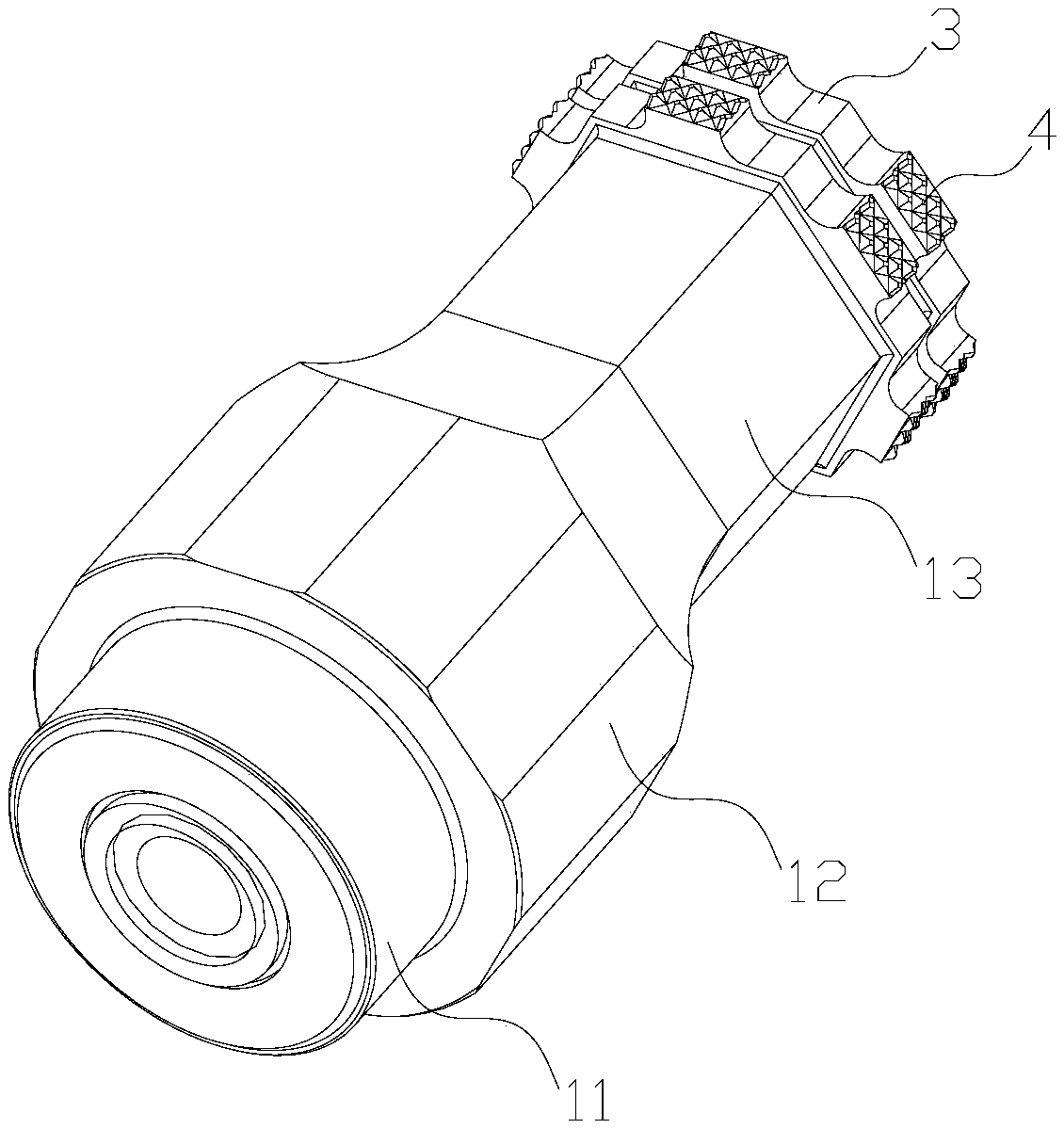
[0052] Such as Image 6 As shown, the difference between Embodiment 4 and Embodiment 3 is that the cross section of the transmission rod 13 is a regular octagon, and the welding end 3 is a cylinder with a cross section of a regular octagon, and each side of the transmission rod 13 is connected to the The sides of the welding end 3 are parallel.
PUM
 Abstract
Description
Claims
Application Information