Circular pipe automatic cutting machine

A round pipe and cutting machine technology, applied in metal processing machinery parts, large fixed members, clamping and other directions, can solve the problems of large parallelism error of the end face of the steel pipe, large waste of materials, low processing accuracy, etc., to increase cutting Accuracy, convenient and practical processing, reasonable structure and layout

Pending Publication Date: 2019-04-05
浙江益森久城环保设备有限公司 +1
View PDF5 Cites 1 Cited by
  • Summary
  • Abstract
  • Description
  • Claims
  • Application Information

AI Technical Summary

Problems solved by technology

[0002] At present, when cutting steel pipes in the society, the feeding, cutting and other processes are completely manually operated. If a large batch of cutting is required, it needs to be moved and positioned multiple times. The operation is troublesome, the work efficiency is low, and the labor intensity is high.
[0003] There are three main types of equipment for cutting steel pipes. One is the sawing machine cutting method. The parallelism error of the end face of the steel pipe cut by this method is large and the processing accuracy is low; the second method is the turning method. The steel pipe rotates with the spindle at high speed, and the cutting knife The steel pipe is cut by feeding in a straight line perpendicular to the axis of the steel pipe. Since the iron filings are not easy to break, this cutting method is not suitable for cutting large-diameter steel pipes. The third method is the milling method. The steel pipe is fixed and the tool rotates at high speed. And cut the steel pipe by feeding in a straight line perpendicular to the axis of the steel pipe. Due to the limitation of the diameter of the tool, this cutting method is not suitable for cutting large-diameter steel pipes; the cutting force of turning and milling is relatively large. The strength of the tool, the cutting edge of the tool is relatively wide, the incision formed on the steel pipe is also wide, and the material to be cut is wasted.
The above three cutting methods can only cut one workpiece blank in one feed, and the processing efficiency is also low

Method used


Image

  • Circular pipe automatic cutting machine
  • Circular pipe automatic cutting machine
  • Circular pipe automatic cutting machine

Examples


Embodiment Construction

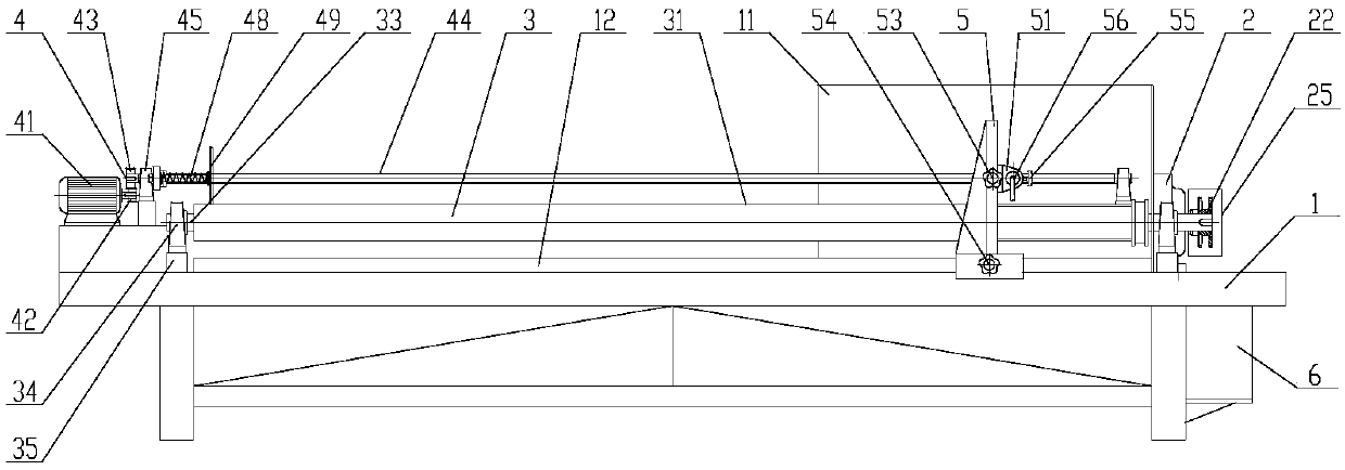
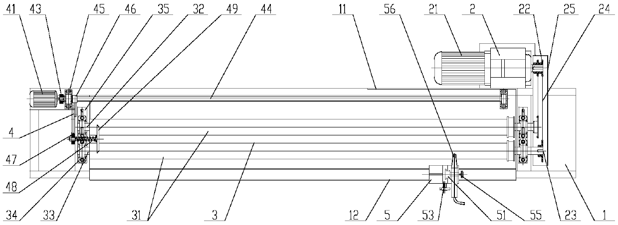
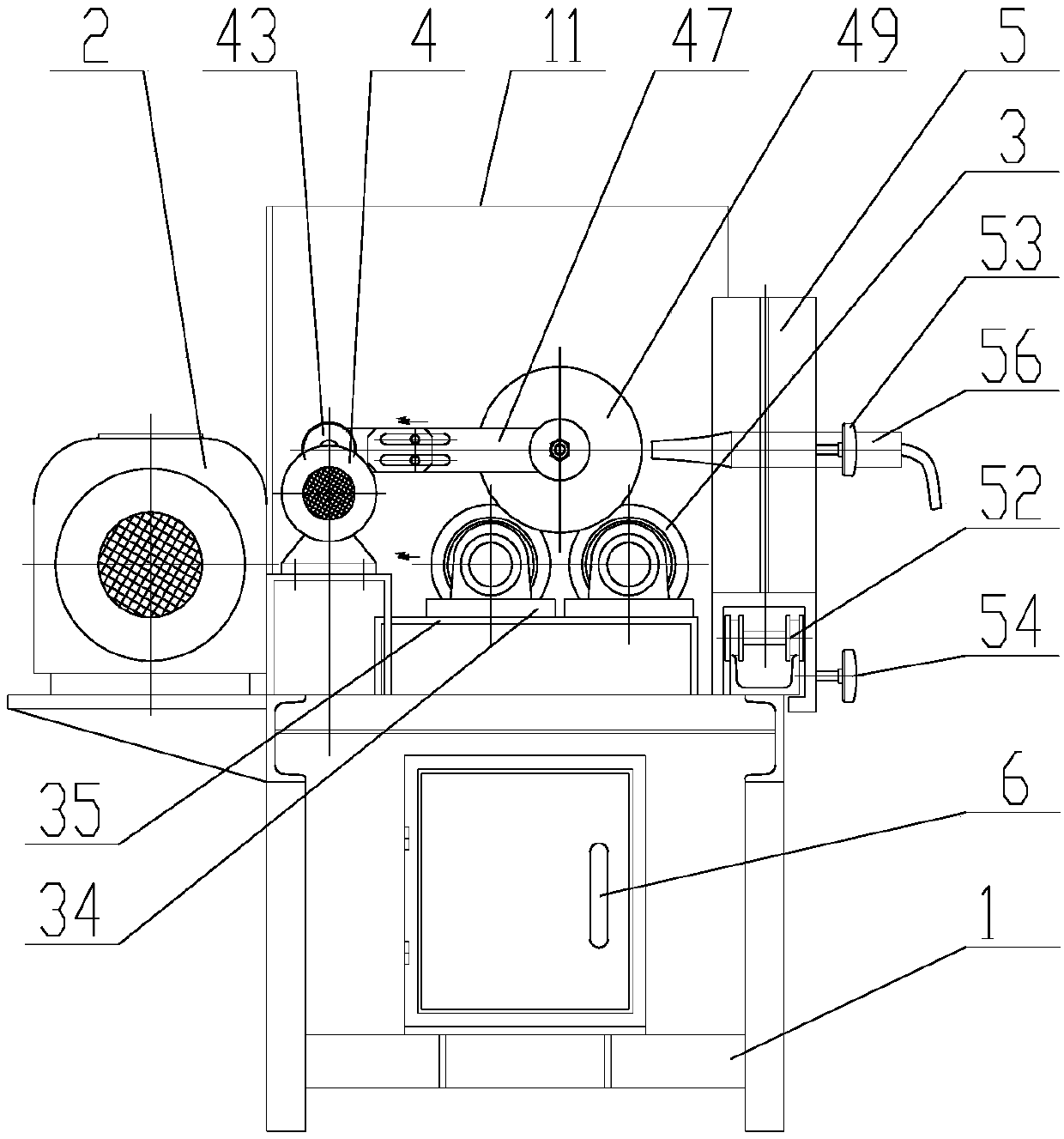
[0019] Such as Figure 1-4 As shown, a circular pipe automatic cutting machine includes a frame 1, a workpiece supporting mechanism 3 arranged on the frame 1, a host drive system 2 arranged at one end of the workpiece supporting mechanism 3, and a The automatic pipe feeding system 4 at the other end of the workpiece support mechanism 3 and the tool rest control device 5 arranged on the workpiece support mechanism 3, the one end of the workpiece support mechanism 3 is also provided with an electric control box 6, and the electric control box 6 It is arranged under the main engine transmission system 2; the main engine transmission system 2 can drive the workpiece support mechanism 3 to rotate; when cutting a circular tubular workpiece, the workpiece is placed on the workpiece support mechanism to support the workpiece Function, it is convenient to make the tool holder control device and the workpiece on the same level, so as to facilitate the cutting of the circular tube workpi...


PUM


Abstract

The invention discloses a circular pipe automatic cutting machine which comprises a rack, a workpiece bearing mechanism arranged on the rack, a host transmission system arranged at one end of the workpiece bearing mechanism, an automatic pipe inlet system arranged at the other end of the workpiece bearing mechanism and a knife holder control device arranged on the workpiece bearing mechanism; oneend of the workpiece bearing mechanism is further provided with an electric cabinet; the electric cabinet is arranged below the host transmission system; and the host transmission system can drive theworkpiece bearing mechanism to rotate. The circular pipe automatic cutting machine is reasonable in structure layout, simple in mounting and operation and convenient and practical in processing, realizes cutting automatic pipe inlet, weakens the operation intensity, reduces the cutting period time, improves the efficiency, reduces material waste and ensures the quality of a part due to accurate size of the cut part and thus achieves the purpose of efficient, accurate and safe cutting processing.

Description

technical field [0001] The invention belongs to the technical field of mechanical equipment, in particular to an automatic circular pipe cutting machine. Background technique [0002] At present, when cutting steel pipes in the society, the feeding, cutting and other processes are completely manually operated. If a large batch of cutting is required, it needs to be moved and positioned multiple times. The operation is cumbersome, the work efficiency is low, and the labor intensity is high. [0003] There are three main types of equipment for cutting steel pipes. One is the sawing machine cutting method. The parallelism error of the end face of the steel pipe cut by this method is large and the processing accuracy is low; the second method is the turning method. The steel pipe rotates with the spindle at high speed, and the cutting knife The steel pipe is cut by feeding in a straight line perpendicular to the axis of the steel pipe. Since the iron filings are not easy to brea...

Claims


Application Information

Patent Timeline
Patent Type & Authority Applications(China)
IPC IPC(8): B23Q7/00B23Q1/25B23Q11/00B23Q3/00
CPCB23Q1/25B23Q3/00B23Q7/00B23Q11/00
Inventor 宣汉良徐敏勇阮建根徐涛裘佰钢卢伟强周永建王荣东
Owner 浙江益森久城环保设备有限公司
Why Eureka
Try Eureka