System and method for calibrating tool center point of robot

A tool center point and correction system technology, applied in the field of robot tool center point correction, can solve problems such as robot tool center point correction, and achieve the effect of high correction accuracy

Active Publication Date: 2019-04-05
IND TECH RES INST
View PDF18 Cites 11 Cited by
  • Summary
  • Abstract
  • Description
  • Claims
  • Application Information

AI Technical Summary

Problems solved by technology

[0008] In view of the above problems in the prior art, one of the objectives of the present invention is to provide a robot tool

Method used


Image

  • System and method for calibrating tool center point of robot
  • System and method for calibrating tool center point of robot
  • System and method for calibrating tool center point of robot

Examples


Embodiment Construction

[0048] Embodiments of the robot tool center point calibration system and method thereof according to the present invention will be described below with reference to the accompanying drawings. For the sake of clarity and convenience in the description of the drawings, the sizes and proportions of the components in the drawings may be exaggerated or zoomed out. In the following description and / or claims, when an element is referred to as being "connected" or "coupled" to another element, it may be directly connected or coupled to the other element or there may be intervening elements; and when an element is referred to as " When "directly connected" or "directly coupled" to another element, there are no intervening elements, and other words used to describe the relationship between elements or layers should be interpreted in the same way. To facilitate understanding, the same components in the following embodiments are described with the same symbols.

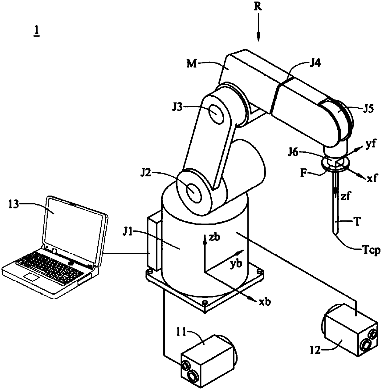
[0049] see figure 1 , ...


PUM


Abstract

The invention discloses a system and method for calibrating the tool center point of a robot. The system may include a first image sensor, a second image sensor, and a controller. The first image sensor may have a first image central axis. The second image sensor may have a second image central axis not parallel to the first image central axis, and intersect the first image central axis at an intersection point. The controller may control a robot to repeatedly move a tool center point thereof between the first and the second image central axis. The controller may record a calibration point including the coordinates of the joints of the robot when the tool center point overlaps the intersection point, and then move the tool center point and repeat the above steps to generate several calibration points, whereby the controller may calculate the coordinate of the tool center point according to the calibration points.

Description

technical field [0001] The invention relates to a robot tool center point correction system, in particular to an automatic robot tool center point correction system. The invention also relates to a robot tool center point correction method of the robot tool center point correction system. Background technique [0002] With the advancement of science and technology, the application of robots in various industries is becoming more and more extensive; generally speaking, a robot is an articulated mechanical arm with multiple joints, and one end is provided with a tool, such as a welding tool or a drill Tools, etc., to perform various tasks; and before the robot performs operations, the position of the tool center point (Tool CenterPoint, TCP) of the tool needs to be precisely corrected in advance, so that the controller of the robot can be based on the tool center Dot enables the tool to run in the correct path. However, the center point correction technology of the robot too...

Claims


Application Information

Patent Timeline
IPC IPC(8): B25J19/00
CPCB25J19/0095B25J9/1692G05B19/4086G05B2219/40611G01B11/005G01B21/042G05B19/4083G05B2219/39007G05B2219/39016
Inventor 黄成凯古有彬陈诣伦杨淳宜陈俊皓
Owner IND TECH RES INST
Why Eureka
Try Eureka