Top span beam for prefabricated building

A kind of architectural and prefabricated technology, applied in the direction of joists, girders, trusses, etc., can solve the problems of inability to achieve common fixation of horizontal and vertical, inability to fine-tune the length of span beams, poor overall adjustment, etc., to achieve convenient support card The seat is fixed, the overall adjustment is increased, and the effect of easy disassembly

Pending Publication Date: 2019-04-05
江苏扬桩金源管业有限公司
View PDF17 Cites 0 Cited by
  • Summary
  • Abstract
  • Description
  • Claims
  • Application Information

AI Technical Summary

Problems solved by technology

[0002] Manufacture of prefabricated buildings is prefabricated building materials in the factory, and then transported to the construction site for assembly. This will be a great revolution faced by my country's construction and building materials industry at the turn of the century. Steel will be used in prefabricated buildings. , steel is also widely used in other construction industries due to its high hardness, corrosion resistance and long service life. It is especially important in use, and the current steel structure top span beam adopts a simple and basic structural form, its overall adjustment is poor, and the length of the span beam cannot be fine-tuned, and the span beam is generally used in conjunction with the beam column, and the span beam The fixation between the beam and the column needs to overcome the lateral force and shear force, but today's prefabricated span beams often ignore these, and cannot achieve both horizontal and vertical fixation, and the installation is complicated and difficult to disassemble

Method used


Image

  • Top span beam for prefabricated building
  • Top span beam for prefabricated building
  • Top span beam for prefabricated building

Examples


Embodiment Construction

[0019] In order to make the technical means, creative features, goals and effects achieved by the present invention easy to understand, the present invention will be further described below in conjunction with specific embodiments.

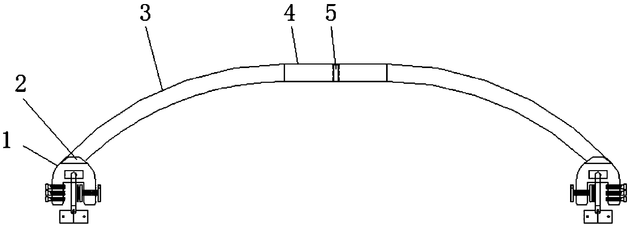
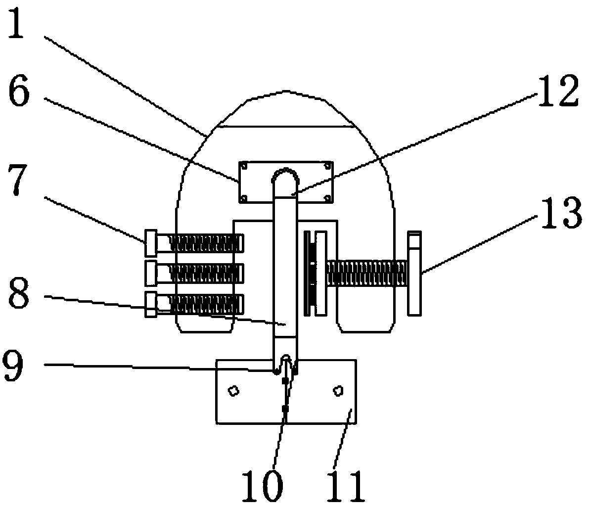
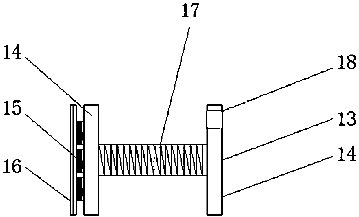
[0020] Such as Figure 1-5 As shown, a top span beam for a prefabricated building includes a support bracket 1, the support bracket 1 is welded with one end of a curved beam 3 through a welding joint 2, and the other end of the curved beam 3 is integrally formed with a straight beam 4. A fixed piece 6 is bolted to the front top of the support holder 1, and a telescopic tube 19 is arranged in the middle of the fixed piece 6, and the other end of the telescopic tube 19 is fixedly connected to a long tube 8 through a connecting elbow 12. The other end of the long pipe 8 is threadedly connected with a connecting block 10, the bottom of the connecting block 10 is connected with a positioning flap 11 through a fixing bolt 9, and one side of the support ...


PUM


Abstract

The invention discloses a topspan beam for a prefabricated building. The beam comprises a support clamping seat, the support clamping seat is welded with one end of a curved beam through a welded joint, the other end of the curved beam is integrally formed with a straight beam, a fixing seatis connected to one side of a circular plate through a threaded post, and the other side of the circular plate is fixedly connected to a contact plate by a spring. Through the cooperation clamping of the straight beam and an embedded beam, the transverse length of the span beam can be conveniently finely adjusted during the installation process, the overall adjustability is increased, through asymmetric cooperation fixing ofa clamping bolt and the fixing seat, a transverse position conveniently locks the support clamping seat on a beam column, a telescopic tube is arranged to facilitate the adjustment of the protruding position of a positioning folding plate, thereby facilitating the fixing of the support clamping seat of a longitudinal position,the positioning folding plate is arranged to facilitate the adjustment of a folding angle of the positioning folding plate, the beam can be convenientlyapplied to the fixing of beam columnsof different shapes, the overall structure is easy to disassemble, the disassembly and assembly are convenient, and the fixing is good.

Description

technical field [0001] The invention relates to the technical field of prefabricated buildings, in particular to a top span beam for prefabricated buildings. Background technique [0002] Manufacture of prefabricated buildings is prefabricated building materials in the factory, and then transported to the construction site for assembly. This will be a great revolution faced by my country's construction and building materials industry at the turn of the century. Steel will be used in prefabricated buildings. , steel is also widely used in other construction industries due to its high hardness, corrosion resistance and long service life. It is especially important in use, and the current steel structure top span beam adopts a simple and basic structural form, its overall adjustment is poor, and the length of the span beam cannot be fine-tuned, and the span beam is generally used in conjunction with the beam column, and the span beam Fixing with beams and columns needs to overcom...

Claims


Application Information

Patent Timeline
Patent Type & Authority Applications(China)
IPC IPC(8): E04C3/04
CPCE04C3/04
Inventor 毛晓珏顾磊赵正宏祁猛
Owner 江苏扬桩金源管业有限公司
Why Eureka
Try Eureka