A safe and efficient high-voltage current limiting device for electrical equipment

A technology of electrical equipment and current limiting devices, which is applied in the direction of circuit devices, emergency protection circuit devices, and emergency protection circuit devices for limiting overcurrent/overvoltage, etc. Loss, harm reduction, current suppression effects

Active Publication Date: 2020-10-16
STATE GRID XINJIANG ELECTRIC POWER CO ECONOMIC TECH RES INST +3
View PDF7 Cites 0 Cited by
  • Summary
  • Abstract
  • Description
  • Claims
  • Application Information

AI Technical Summary

Problems solved by technology

[0007] (2) The existing design cannot repair the power line under the condition of uninterrupted power supply

Method used


Image

  • A safe and efficient high-voltage current limiting device for electrical equipment
  • A safe and efficient high-voltage current limiting device for electrical equipment
  • A safe and efficient high-voltage current limiting device for electrical equipment

Examples


Embodiment 1

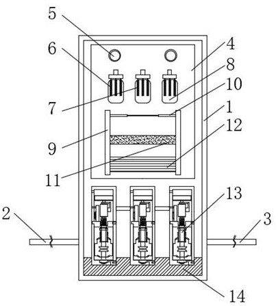
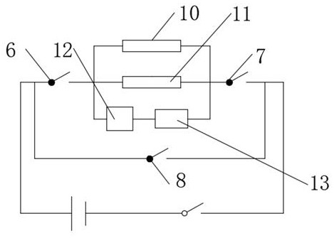
[0031] see Figure 1-2 , a safe and efficient high-voltage current limiting device for electrical equipment, comprising a power distribution cabinet 1 and an integrated circuit board 4, the lower end of the power distribution cabinet 1 is fixedly connected with an incoming wire 2 and an outgoing wire 3, and the integrated circuit board 4 is fixedly installed on Inside the power distribution cabinet 1, the electric wire 2 and the outgoing wire 3 are electrically connected to the integrated circuit board 4, the upper end of the integrated circuit board 4 is fixedly installed with a status indicator 5, and a first isolation switch 6 is arranged below the status indicator 5. The second isolation switch 7 and the third isolation switch 8, the first isolation switch 6, the second isolation switch 7 and the third isolation switch 8 are fixedly connected to the integrated circuit board 4, and the integrated circuit board 4 is also fixedly connected There is a conductive support 9, and...

Embodiment 2

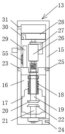
[0034] see Figure 3-6 , the basis of Embodiment 1 is different in that the vacuum eddy current switch 13 includes an epoxy resin pole 15, the inner wall of the epoxy resin pole 15 is fixedly connected with a shielding plate 16, and the bottom of the shielding plate 16 is provided with The vacuum interrupter 17 and the shielding plate 16 are also fixedly connected with a bellows 18, the inside of the bellows 18 is movably connected with a movable conductive rod 19, and the bottom end of the movable conductive rod 19 is fixedly connected with a movable contact 20, the bottom of the movable contact 20 A fixed conduction rod 21 is provided, and the fixed conduction rod 21 is fixedly connected to the bottom end of the epoxy resin pole 15, and the top end of the fixed conduction rod 21 is fixedly connected to a fixed contact 22, and a movable cover plate 23 is also provided above the shielding plate 16 , the bottom end of the epoxy resin pole 15 and the movable cover plate 23 are r...

Embodiment 3

[0041] see Figure 7 , the difference with the basis of Embodiment 2 is that the controller 55 includes a housing 44, the housing 44 is fixedly connected with the limit post 45, and the inside of the housing 44 is fixedly installed with the lower terminal 46, the lower terminal 46 is provided with a guide hole 47 and a lower contact end 48, a ceramic thermistor 49 is fixedly installed above the lower terminal 46, a high-resistance shrapnel 50 is fixedly installed above the ceramic thermistor 49, and the top of the housing 44 is fixedly connected with a top The inside of the shell 51 and the top shell 51 are fixedly equipped with a curved elastic piece 52 , and an upper terminal 53 is fixedly connected to the side wall of the top shell 51 , and an upper contact end 54 is arranged on the upper terminal 53 .

[0042] When in use, the controller 55 senses the abnormal current generated when the circuit is short-circuited, and the high-resistance shrapnel 50 will bend, thereby push...


PUM


Abstract

The invention discloses a safe and efficient high voltage current limiting device of an electrical device, belonging to the technical field of current limiting devices. A safe and efficient high voltage current limiting device of an electrical device includes a power distribution cabinet and an integrated circuit board, a lower end of the power distribution cabinet is in fixedly connected with aninput conductor and an output conductor, the integrated circuit board is fixedly installed inside the power distribution cabinet, the input conductor and the output conductor are electrically connected to the integrated circuit board, a status indicator is fixedly installed on an upper end of the power distribution cabinet, whether a circuit of the electrical device is in a normal working state can be observed visually through the status indicator, a first disconnector, a second disconnector and a third disconnector are arranged below the status indicator, and the first disconnector, the second disconnector and the third disconnector are fixedly connected with the integrated circuit board. The safe and efficient high voltage current limiting device of the electrical device effectively solves problems that huge reactive power loss is caused by an existing design connected in a circuit in series, and that a power line cannot be maintained when the power is cut off.

Description

technical field [0001] The invention relates to the technical field of current limiting devices, in particular to a safe and efficient high-voltage current limiting device for electrical equipment. Background technique [0002] With the development of economy, the sharp increase of electric load, and the increase of grid capacity, the impact of increasing short-circuit current on electrical equipment of power system is also increasing; at the same time, it is difficult for existing circuit breakers to break huge short-circuit current. Therefore, in order to solve this major problem, the way that the current-limiting element is connected in series in the circuit is widely used in the power transmission and distribution system of the power system, and at the same time, the high-voltage current-limiting device for electrical equipment has also emerged as the times require. [0003] At present, when the high-voltage current-limiting devices of electrical equipment on the market...

Claims


Application Information

Patent Timeline
Patent Type & Authority Patents(China)
IPC IPC(8): H02H9/08
CPCH02H9/08
Inventor 梁钢吕盼陈伟伟赵志强李海峰辛超山边家瑜付高善薛静杰纪凤坤王新刚张艳左雅余中平孙立成任娟吴高磊哈丽旦·吐尔逊于志勇朱国平李宝鹏吴伟丽刘勇刘俊
Owner STATE GRID XINJIANG ELECTRIC POWER CO ECONOMIC TECH RES INST
Why Eureka
Try Eureka