An environmentally friendly manual trimming device for metal products of auto parts

A technology for metal products and auto parts, which is applied in the field of manual trimming devices for metal products of environment-friendly auto parts. Effects of water resources and ensuring the quality of the working environment

Active Publication Date: 2020-08-14
梁山鸿福交通设备有限公司
View PDF8 Cites 0 Cited by
  • Summary
  • Abstract
  • Description
  • Claims
  • Application Information

AI Technical Summary

Problems solved by technology

[0002] When the metal products of auto parts are used, they often trim the metal products and cut them into the required shape. The metal products are often trimmed by mechanical drive or manual drive. The existing manual metal product trimming device is used for cutting Often only one side of the metal product can be trimmed when cutting, and the efficiency is relatively slow. Similarly, when cutting the edge, the waste is not removed in time, which not only affects the quality of the working environment, but also affects the quality of the metal product. The clamp fixes the metal product to avoid the displacement of the trimming position caused by the movement of the metal product when cutting the edge. However, the existing metal product fixing fixture has a single function and can only fix one kind of metal product. Metal products are generally divided into square or round , when trimming, it is necessary to switch back and forth between the two fixtures, the work efficiency is slow, and the cost is high. At the same time, the clamping adjustment operation of the fixture is cumbersome and the clamping speed is slow. Therefore, we propose an environmentally friendly car Manual trimming device for accessory metalwork

Method used


Image

  • An environmentally friendly manual trimming device for metal products of auto parts
  • An environmentally friendly manual trimming device for metal products of auto parts
  • An environmentally friendly manual trimming device for metal products of auto parts

Examples


Embodiment Construction

[0024] The following will clearly and completely describe the technical solutions in the embodiments of the present invention with reference to the accompanying drawings in the embodiments of the present invention. Obviously, the described embodiments are only some, not all, embodiments of the present invention. Based on the embodiments of the present invention, all other embodiments obtained by persons of ordinary skill in the art without making creative efforts belong to the protection scope of the present invention.

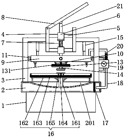
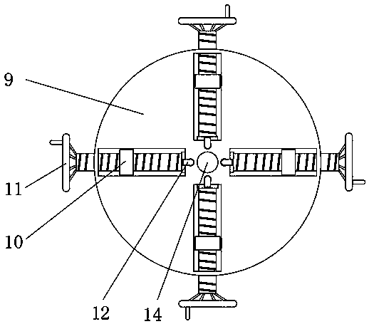
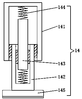
[0025] see Figure 1-5 , the present invention provides a technical solution: an environment-friendly manual trimming device for metal products of auto parts, including a base 1, a workbench 2 is arranged on the top of the base 1, and L-shaped brackets 3 are symmetrically arranged on the left and right sides of the top of the workbench 2 Two groups of L-shaped brackets 3 top adjacent surfaces are welded with vertical rods 4, two groups of support columns 5 are...


PUM


Abstract

The invention discloses an environment-friendly manual edge cutting device for automobile accessory metal products in the technical field of metal product machining. A base is included. The outer wallof a guide rod is sequentially sleeved with a limiting block and a reset spring from top to bottom. A pressing rod is hinged to the top of a vertical rod on the left side. The bottom of the guide rodis connected with a bearing block. Blades are arranged at the bottom of a movable block. A clamp is arranged at the center of the top of the workbench. Nozzles are arranged on the sides, close to theblades, of connecting water pipes. The four blades are arranged at the bottom of the bearing block, meanwhile, the four blades are arranged on the movable block, the movable block is connected with an adjusting screw, the edge cutting position needs to be adjusted, the adjusting screw is rotated to drive the movable block to move in a sliding groove so that the positions of the blades can be adjusted, and different requirements of users are met. When the blades downwards conduct edge cutting, a grinding wheel sheet rubs with the metal product edge cutting position, burrs at the metal productedge cutting position are removed, and the metal product edge cutting quality is improved.

Description

technical field [0001] The invention relates to the technical field of metal product processing, in particular to an environment-friendly manual trimming device for metal products of auto parts. Background technique [0002] When the metal products of auto parts are used, they often trim the metal products and cut them into the required shape. The metal products are often trimmed by mechanical drive or manual drive. The existing manual metal product trimming device is used for cutting Often only one side of the metal product can be trimmed when cutting, and the efficiency is relatively slow. Similarly, when cutting the edge, the waste is not removed in time, which not only affects the quality of the working environment, but also affects the quality of the metal product. The clamp fixes the metal product to avoid the displacement of the trimming position caused by the movement of the metal product when cutting the edge. However, the existing metal product fixing fixture has a...

Claims


Application Information

Patent Timeline
Patent Type & Authority Patents(China)
IPC IPC(8): B23P23/04
CPCB23P23/04
Inventor 李国志刘玲玲
Owner 梁山鸿福交通设备有限公司
Why Eureka
Try Eureka