Simple leveling worktable used for electric spindle drilling

A technology of electric spindle and workbench, which is applied in the direction of boring/drilling, drilling/drilling equipment, manufacturing tools, etc., to achieve low failure rate, easy processing and installation, and reduce extra workload.

Inactive Publication Date: 2019-04-09
WUHU HIT ROBOT TECH RES INST
View PDF4 Cites 4 Cited by
  • Summary
  • Abstract
  • Description
  • Claims
  • Application Information

AI Technical Summary

Problems solved by technology

[0003] In view of the above problems, the present invention proposes a simple leveling workbench for electric spindle drilling, which solves the problem of electric spindle drilling leveling by providing two compression structures and a joint bearing support shaft

Method used


Image

  • Simple leveling worktable used for electric spindle drilling
  • Simple leveling worktable used for electric spindle drilling
  • Simple leveling worktable used for electric spindle drilling

Examples


Embodiment 1

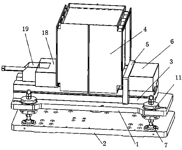
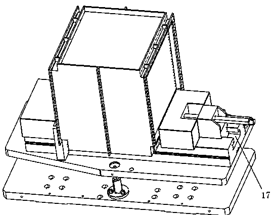
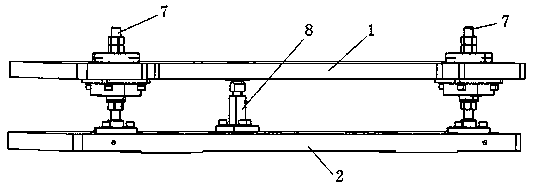
[0020] according to Figure 1-Figure 7 As shown, this embodiment provides a simple leveling workbench for electric spindle drilling, including a leveling plate 1 and a support plate 2, and a base 3 is provided on the upper surface of the leveling plate 1 for installing heat dissipation 4, the radiator 4 is connected with the fixed clamp 6 through the spacer 5, the left and right symmetrical support shaft 7 is provided at one end of the leveling plate 1 and the support plate 2, and the joint bearing support shaft 8 is provided at the middle of the other end, The upper end of the joint bearing support shaft 8 is provided with a joint bearing seat 9 for installing the joint bearing 10 , and the joint bearing seat 9 is connected with the leveling plate 1 . A compression spring 11 is provided on the support shaft 7, a spring upper cover 12 is provided on the support shaft positioned above the leveling plate 1, and a spring lower cover 13 is arranged on the support shaft positioned ...

Embodiment 2

[0022] A small horizontal observation device is installed on the leveling plate to make the adjustment process more convenient. In addition, a power device and a feedback structure are provided under the adjustment nut, so that the user's manual adjustment becomes automatic adjustment, and the data of the feedback structure is transmitted to the system.

[0023] In the present invention, two compression structures and a joint bearing support shaft 8 are arranged in the middle of the leveling plate 1 and the support plate 2 to achieve the supporting effect, wherein the joint bearing support shaft 8 is provided with a rotatable joint bearing 10, which can be operated by The adjustment nut 15 can easily adjust the horizontal position of the leveling plate 1, and the spring lower cover 13 is tightly pressed on the adjustment nut 15 by the compression spring 11 to ensure that there is no movement in the work engineering. The present invention uses the compression spring 11 to make t...


PUM


Abstract

The invention discloses a simple leveling worktable used for electric spindle drilling. The worktable comprises a leveling plate and a supporting plate; a base is arranged on the upper surface of theleveling plate and used for mounting of a radiator, the radiator is connected with a fixed clamp through a cushion block, supporting shafts which are in left and right symmetry are arranged on one endof the leveling plate and one end of the supporting plate, knuckle bearing supporting shafts are arranged in the middles of the other ends, knuckle bearing bases are arranged at the upper ends of theknuckle bearing supporting shafts and are used for mounting of knuckle bearings, and the knuckle bearing bases are connected with the leveling plate. Through arrangement of two compression structuresand one knuckle bearing supporting shaft, electric spindle drilling leveling problem can be solved.

Description

technical field [0001] The invention relates to the technical field of electric spindles, in particular to a simple leveling workbench for electric spindle drilling. Background technique [0002] With the rapid development of the automation industry, various tasks that were previously done manually are gradually replaced by automation, and various non-standard drilling parts can be replaced by robots and automation. Many of the workpiece shapes are non-processing surfaces, so there is a leveling requirement for the workbench. Among them, the automatic adjustment by sensors is costly and complex, and the adjustment process by pure stud connections is cumbersome. The current technology mostly uses ordinary screw leveling. The leveling process is very complicated, with many processes and takes a long time. Or automatic automatic adjustment is used, which has a complex structure and high cost. It is not suitable for places with low frequency of loading and unloading. Therefore...

Claims


Application Information

Patent Timeline
Patent Type & Authority Applications(China)
IPC IPC(8): B23Q1/25B23B41/00
CPCB23B41/00B23Q1/25
Inventor 徐华明陈建曹雏清高云峰
Owner WUHU HIT ROBOT TECH RES INST
Why Eureka
Try Eureka