Workpiece turnover and correction mechanism based on image identification

A technology of overturning correction mechanism and overturning mechanism, which is applied to conveyor objects, transportation and packaging, etc., can solve the problems of reduced product reliability and stability, increased labor intensity, and increased uncertain factors, so as to improve efficiency, Easy to operate, cleverly designed effects

Inactive Publication Date: 2019-04-09
NANCHANG UNIV
View PDF6 Cites 10 Cited by
  • Summary
  • Abstract
  • Description
  • Claims
  • Application Information

AI Technical Summary

Problems solved by technology

[0002] In the current industrial automation production line, the process is relatively scattered, and the work of flipping and correcting the workpiece is generally done manually, which results in more uncertain factors, increased labor intensity, and greatly reduced product reliability and stability. ; At the same time, it will also bring about an increase in labor costs and a reduction in work efficiency
The technical problem to be solved in the present invention is: when the flip correction device on the existing industrial automation production line adopts manipulators and numerical control robots to detect and flip the workpiece, it also needs to make corresponding special fixtures. Custom-made fixtures are not only time-consuming and laborious, And the cost is relatively expensive, not economical enough

Method used


Image

  • Workpiece turnover and correction mechanism based on image identification
  • Workpiece turnover and correction mechanism based on image identification
  • Workpiece turnover and correction mechanism based on image identification

Examples


Embodiment Construction

[0025] For ease of understanding, the present invention will be further described below in conjunction with the accompanying drawings and specific examples.

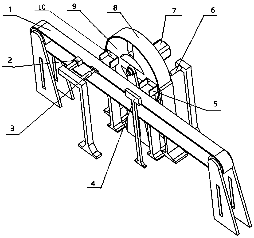
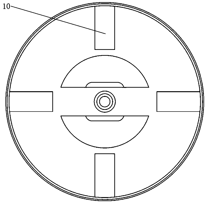
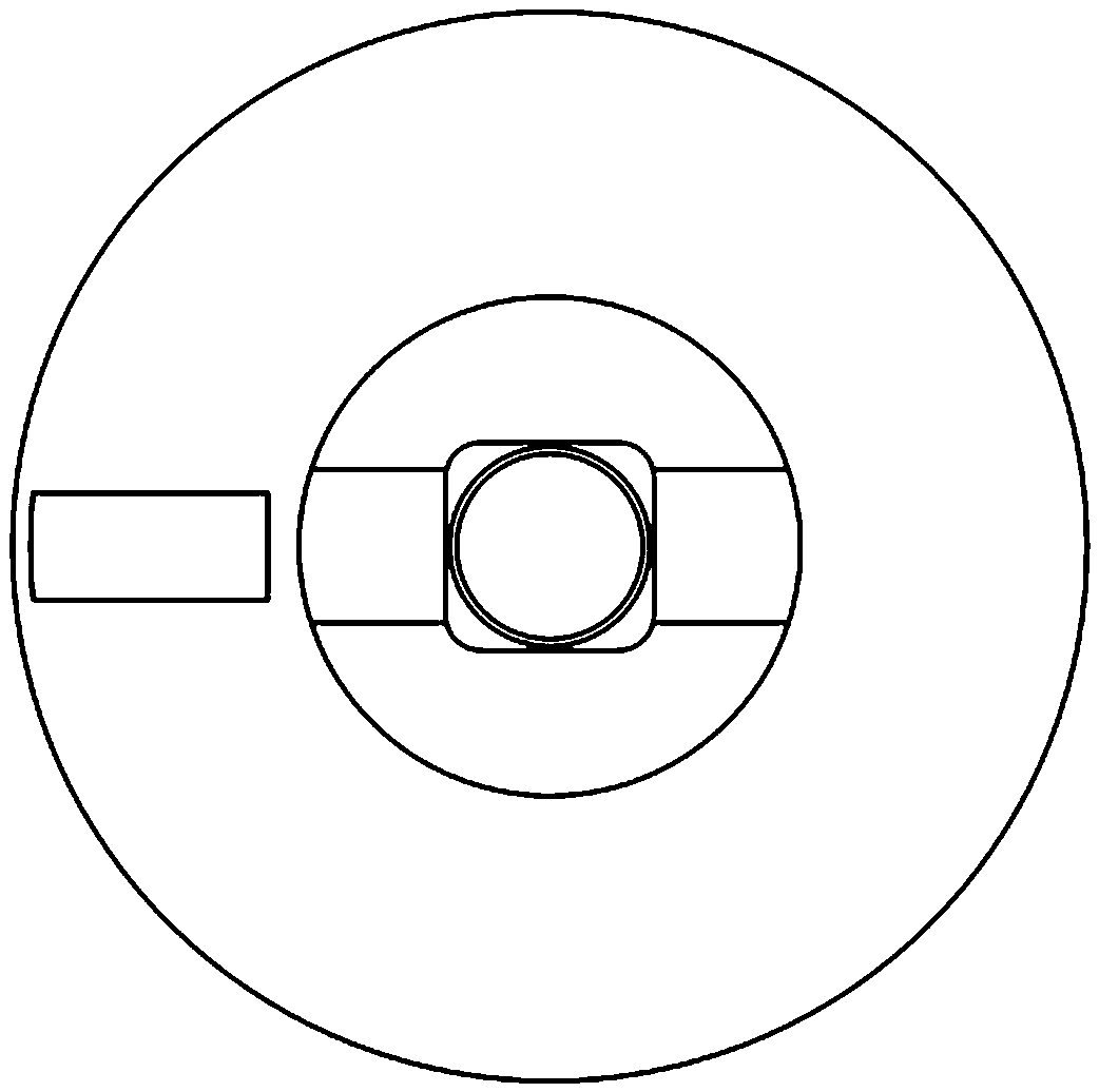
[0026] see figure 1 — Figure 5 , the present invention discloses a workpiece inversion correction mechanism based on image recognition, which includes a conveyor belt 1 for workpiece transmission, one side of the conveyor belt 1 is provided with an inversion mechanism 9, and both sides of the inversion mechanism 9 are equipped with internal Cavity-type storage space, two transition platforms 5 are provided on the side of the storage space close to the conveyor belt 1, and the transition platform 5 is aligned with the conveyor belt 1 and provided with a workpiece entrance, that is, figure 1 Among them, the rear of the two transition platforms 5 continues to extend into the turning mechanism 9, and there are two rectangular cavities for holding workpieces. The turning mechanism 9 and its storage space are driven by the s...


PUM


Abstract

The invention provides a workpiece turnover and correction mechanism based on image identification, and the workpiece turnover and correction mechanism is used for an industrial production line. The workpiece turnover and correction mechanism based on image identification comprises a conveyor belt, wherein a turnover mechanism is arranged on one side of the conveyor belt; intracavity type storagespaces are arranged on the two sides of the turnover mechanism; two transition platforms are arranged on the sides, close to the conveyor belt, of the outer parts of the storage spaces; the transitionplatforms are provided with workpiece inlets aligning at the conveyor belt; the rear parts of the two transition platforms continuously extend into the turnover mechanism; two rectangular cavities are arranged for holding workpieces; the turnover mechanism and the storage spaces are driven by a servo motor so as to intermittently turn over at 90 degrees; the servo motor is connected with a rotaryshaft of the turnover mechanism through a coupler; a first push rod and a second push rod are arranged on the two sides of the conveyor belt and are driven by an air cylinder or a hydraulic cylinder;the two push rods align at the transition platforms according to the opposite direction from two sides of the conveyor belt in the rears of the transition platforms; and an image processing unit directly facing the conveyor belt is arranged in front of the first push rod. According to the workpiece turnover and correction mechanism based on image identification provided by the invention, the costcan be greatly reduced, and the efficiency is improved.

Description

technical field [0001] The invention belongs to the field of mechanical manufacturing and automation thereof, in particular to an image-based workpiece reversal correction mechanism, and discloses its use method, which is used for workpiece placement state judgment and reversal correction on industrial production lines. Background technique [0002] In the current industrial automation production line, the process is relatively scattered, and the work of flipping and correcting the workpiece is generally done manually, which results in more uncertain factors, increased labor intensity, and greatly reduces the reliability and stability of the product. ; At the same time, it will also bring about the increase of labor costs and the problem of reduced work efficiency. The technical problem to be solved in the present invention is: when using the flip correction device on the existing industrial automation production line to detect and flip the workpiece with manipulators and nu...

Claims


Application Information

Patent Timeline
Patent Type & Authority Applications(China)
IPC IPC(8): B65G47/248
CPCB65G47/248
Inventor 肖佳明冯艳汪烨胡瑢华王飞文
Owner NANCHANG UNIV
Why Eureka
Try Eureka