Supercharge Your Innovation With Domain-Expert AI Agents!

Control box used for double-shift draining valve, and draining valve provided with control box

A control box and drain valve technology, applied in the field of sanitary ware, can solve the problems that the full row and half row can be out of control at the same time, the discharge volume of the drain valve is different, and the discharge volume is unstable, etc., and achieves ingenious structural design, reliable function and compact structure Effect

Pending Publication Date: 2019-04-09
XIAMEN R&T PLUMBING TECH
View PDF0 Cites 0 Cited by
  • Summary
  • Abstract
  • Description
  • Claims
  • Application Information

AI Technical Summary

Problems solved by technology

When draining water, pull the toggle with your hand to drive the rotating part to rotate, and then start the drain valve through the starting part to drain water. After releasing your hand, the toggle resets, and the rotating part and the starting part reset. This completes a draining action, but in this structure , it is necessary to loosen the toggle to reset the toggle, and then the rotating part and the starting part can be reset. Since the starting part cannot reset by itself, the drainage of the drain valve will vary depending on the length of time for different people to pull the toggle, and the drainage will be unstable.
[0003] In order to solve the above problems, in the prior art, there is an out-of-control structure designed in the toggle control box of the drain valve, so that after the toggle is pulled in place, the control will be removed, and the starting part of the drain valve can reset itself, thereby solving the problem of drainage. The problem of instability, however, the existing toggle control box with a drain valve with a detachable structure cannot realize the function of full discharge and half discharge at the same time, and is not suitable for full discharge and half discharge. Drain valve

Method used


Image

  • Control box used for double-shift draining valve, and draining valve provided with control box
  • Control box used for double-shift draining valve, and draining valve provided with control box
  • Control box used for double-shift draining valve, and draining valve provided with control box

Examples


no. 1 example

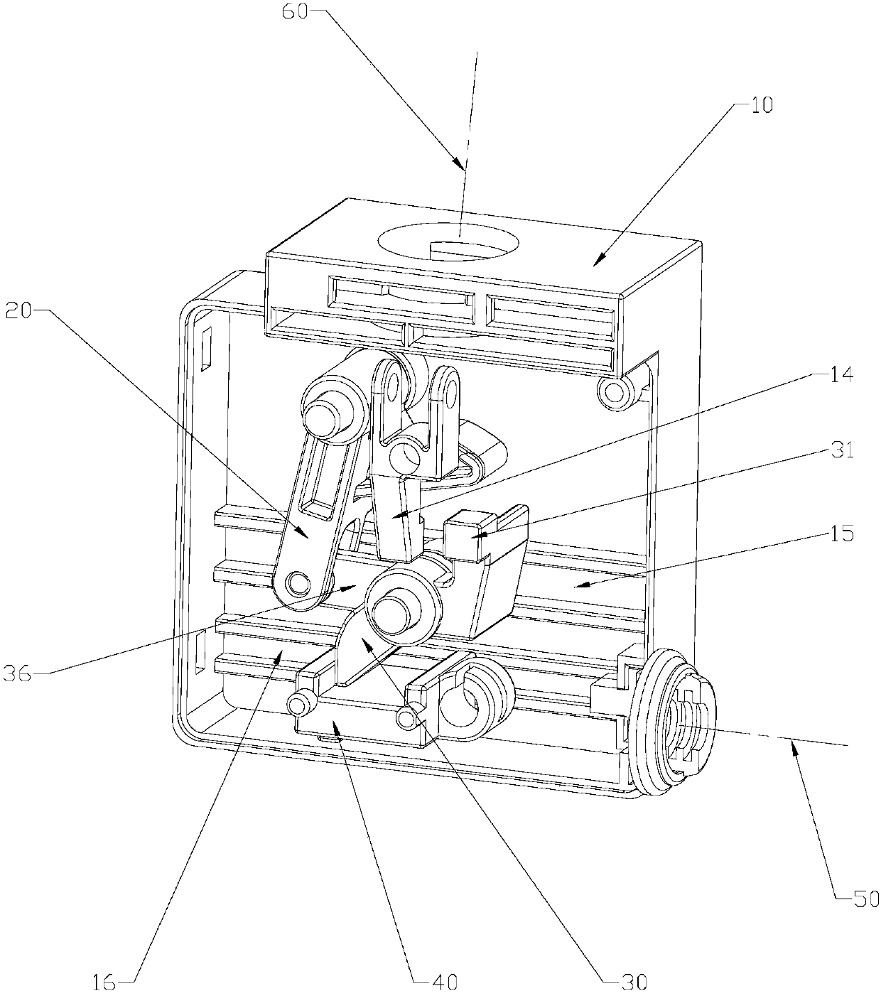
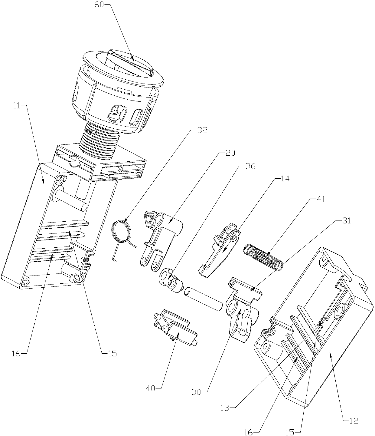
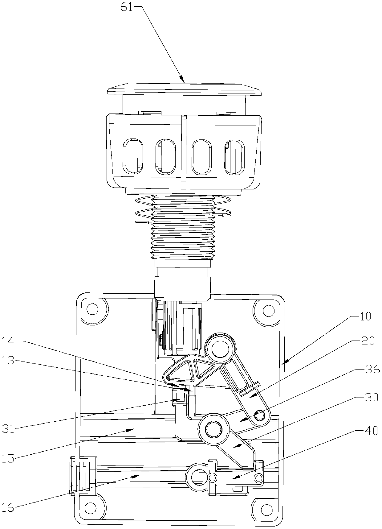
[0060] Such as Figure 1 to Figure 4 As shown, in this embodiment, the transmission body 30 is mounted on the box body 10 in a manner of swinging and sliding; The two ends of the rod 36 are pivotally engaged with the rotating body 20 and the transmission body 30 respectively; Cooperating abutment block 31 . When the transmission body 30 moves to match with the full-row limit block 13 or the half-row limit block 14, under the action of the full-row limit block 13 or the half-row limit block 14 The movement gives way, so that the transmission between the rotating body 20 and the sliding body 40 is disconnected.

[0061] The full row of limit blocks 13 are fixedly arranged on the box body 10, and the half row of limit blocks 14 are movably arranged on the box body 10. In this embodiment, the half row of limit blocks 14 swing Or slidingly mounted on the box body 10; on the movement stroke of the rotating body 20, the transmission body 30 and the sliding body 40, the half-row li...

no. 2 example

[0074] Such as Figure 5 and Figure 6 As shown, the main difference between this embodiment and the first embodiment is: in this embodiment, no connecting rod 36 is provided between the rotating body 20 and the transmission body 30, and the first sliding groove 15 is provided On the rotating body 20 , the transmission body 30 is rotatably mounted on the first sliding groove 15 and can slide along the first sliding groove 15 .

[0075] Such as Figure 5 As shown, in the initial state, the transmission body 30 and the sliding body 40 abut against each other.

[0076] Such as Figure 6As shown, when the half-row switch 62 is pressed down, the rotating body 20 is driven to rotate, and the rotating body 20 further pulls the transmission body 30, and the transmission body 30 further drives the sliding body 40 to move; position, the abutment portion 31 of the transmission body 30 abuts and cooperates with the half-row limit block 14, and is limited by the half-row limit block 14...

no. 3 example

[0079] Such as Figure 7 and Figure 8 As shown, the main difference between this embodiment and the first embodiment is: in this embodiment, the transmission body 30 is slidingly fitted with the first sliding groove 15, and the sliding fit includes left and right sliding fit and front and rear sliding fit.

[0080] Such as Figure 7 As shown, in the initial state, the transmission body 30 and the sliding body 40 abut against each other.

[0081] Such as Figure 8 As shown, when the half-row switch 62 is pressed down, the rotating body 20 is driven to rotate, the rotating body 20 drives the connecting rod 36 and further pulls the transmission body 30, and the transmission body 30 slides left and right in the first sliding groove 15 to drive the sliding body 40 movement; when the transmission body 30 moves to the position that cooperates with the half-row limit block 14, it is limited by the half-row limit block 14, and the transmission body 30 slides back and forth in the f...


PUM


Abstract

The invention discloses a control box used for a double-shift draining valve, and the draining valve provided with the control box. The control box comprises a box body, operation switches, a rotatingbody, a sliding body, a transmission body, a trigger assembly, a complete discharge stop block, and a half discharge stop block; the rotating body is designed to be linkage cooperative with a complete discharge switch and a half discharge switch; the rotating body is used for driving the sliding body to slide through the transmission body; the complete discharge switch is operated for linkage with the rotating body, when the rotating body or the transmission body or the sliding body moves to a position realizing cooperation with the complete discharge stop block, under the effect of the complete discharge stop block, movable position changing is realized, and transmission between the rotating body and the sliding body is cut off; the half discharge switch is operated for linkage with therotating body, when the rotating body or the transmission body or the sliding body moves to a position realizing cooperation with the half discharge stop block, under the effect of the half dischargestop block, movable position changing is realized, and transmission between the rotating body and the sliding body is cut off; so that discharge controls of both complete discharge and half dischargeare realized, water discharge amount of complete discharge and half discharge is not influenced by time period, the structure is simple, and the function is reliable.

Description

technical field [0001] The invention relates to the technical field of sanitary ware, in particular to a control box for a dual-speed drain valve and a drain valve with the same. Background technique [0002] Most of the structure of the toggle control box of the traditional drain valve is that the toggle drives the rotating part arranged in the control box to rotate, and the rotating part drives the starting part (such as a pull rope or lifting rod) of the drain valve to move to activate the drain valve for drainage, while The rotating part is generally directly connected with the starting part. When draining water, pull the toggle with your hand to drive the rotating part to rotate, and then start the drain valve through the starting part to drain water. After releasing your hand, the toggle resets, and the rotating part and the starting part reset. This completes a draining action, but in this structure , it is necessary to loosen the toggle to reset the toggle, and then...

Claims


Application Information

Patent Timeline
Patent Type & Authority Applications(China)
IPC IPC(8): E03D1/34
CPCE03D1/34
Inventor 周洪文王兴东王志忠
Owner XIAMEN R&T PLUMBING TECH
Features
  • R&D
  • Intellectual Property
  • Life Sciences
  • Materials
  • Tech Scout
  • Unparalleled Data Quality
  • Higher Quality Content
  • 60% Fewer Hallucinations
Learn More