Centrifugal wind wheel, manufacturing method thereof and centrifugal fan with centrifugal wind wheel

A technology of centrifugal wind wheel and wheel cover, which is applied to components, mechanical equipment, machines/engines, etc. of elastic fluid pumping devices, which can solve the problems of complex design, reduced enterprise competitiveness, and high development costs, and achieve reduction The effects of processing manufacturing costs, improving air flow, and shortening the development cycle

Pending Publication Date: 2019-04-09
ZHONGSHAN EBS TECH CO LTD
View PDF0 Cites 5 Cited by
  • Summary
  • Abstract
  • Description
  • Claims
  • Application Information

AI Technical Summary

Problems solved by technology

This method has a long development cycle and high development costs
At present, the demand for fans in the market is increasing, and different customers have different performance requirements for fans; in the absence of existing matching models, designers and developers need to customize fans according to solutions 2 and 3, and develop a good During the processing and manufacturing of high-end fans, different molds need to be designed according to different cover profiles and blade profiles, and even additional assembly lines and labor costs are required.
On the one hand, this will increase the cost of design and development, on the other hand, it will increase the cost of processing and manufacturing, as well as labor costs; this will inevitably reduce the competitiveness of enterprises
[0008] In addition, in order to meet the different needs of different customers, the existing manufacturing method of the centrifugal wind wheel needs to redesign the entire centrifugal wind wheel, including the redesign of multiple parameters such as the wheel cover, the wheel disc and the wind blade. Complicated, with many modified elements, not easy to produce

Method used


Image

  • Centrifugal wind wheel, manufacturing method thereof and centrifugal fan with centrifugal wind wheel
  • Centrifugal wind wheel, manufacturing method thereof and centrifugal fan with centrifugal wind wheel
  • Centrifugal wind wheel, manufacturing method thereof and centrifugal fan with centrifugal wind wheel

Examples


Embodiment 1

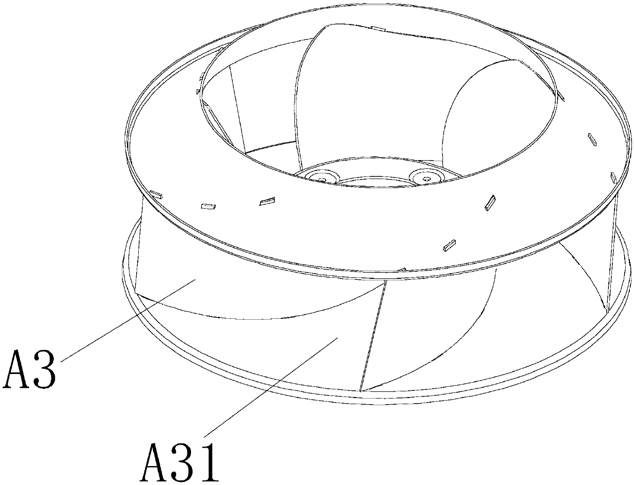
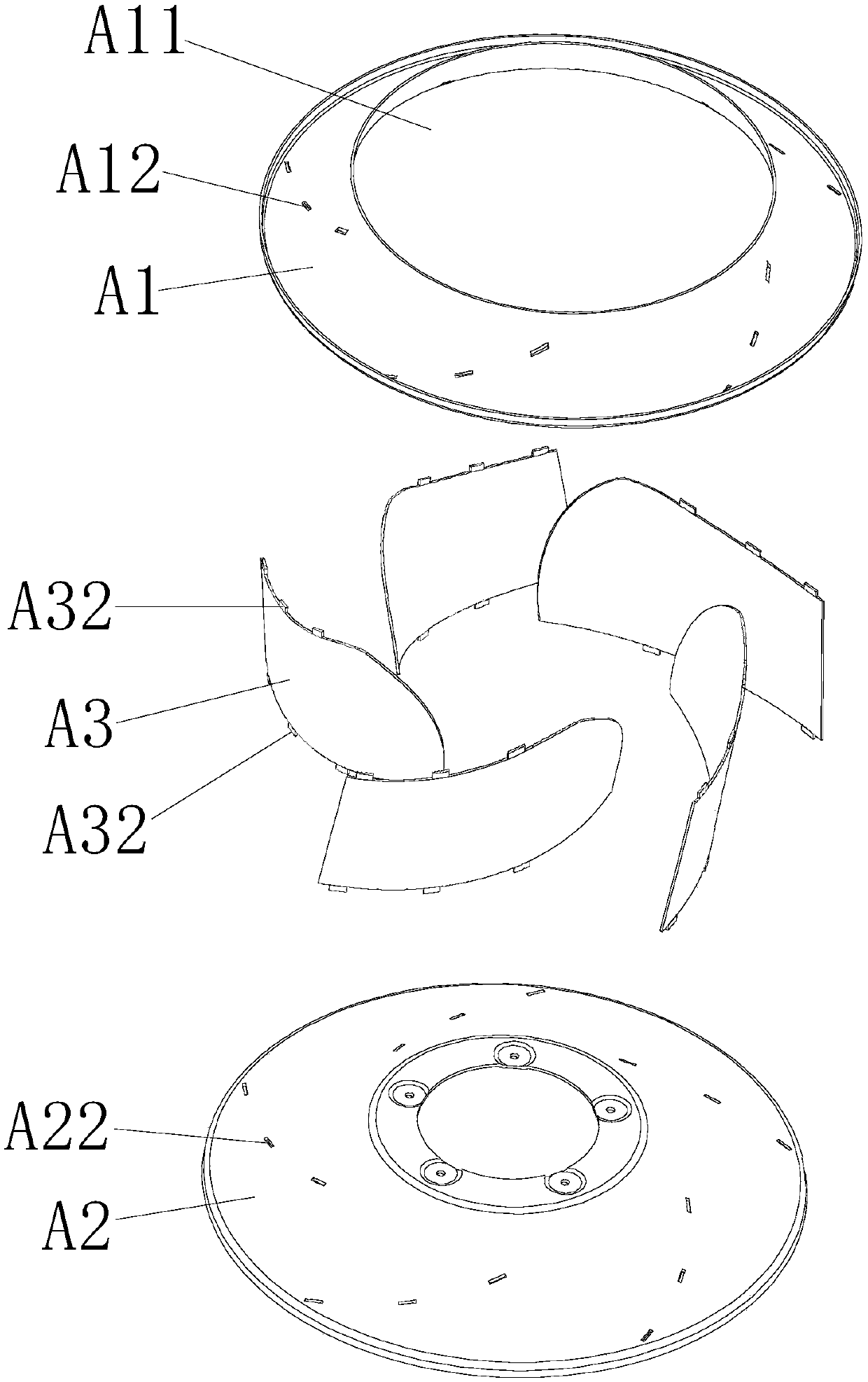
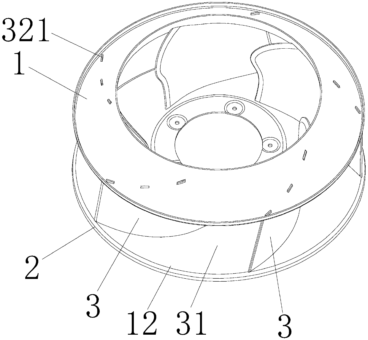
[0074] Such as Figure 3 to Figure 9 As shown, this embodiment is a centrifugal wind wheel, including a wheel cover 1 made of sheet metal, a wheel disc 2 made of sheet metal, and several wind blades 3 made of composite materials installed between the wheel cover 1 and the wheel disc 2 , the wheel cover 1 is provided with an air inlet 11, the center of the wheel disc 2 is provided with a motor installation position 21, an air duct 31 is formed between two adjacent wind blades 3, and an air duct 31 is formed at the end of the air duct 31. The tuyere 12 is characterized in that: the plurality of wind blades 3 made of composite materials include a metal frame 32 and a plastic shell 33 installed on the metal frame 32, and the upper and lower ends of the metal frame 32 are respectively connected to the wheel cover 1 and the wheel disc 2 Together, the thickness H of the plastic shell 33 is varied to improve air flow, the plastic shell 33 and the metal frame 32 are injection molded in...

Embodiment 2

[0105] Such as Figure 10 to Figure 15 As shown, this embodiment is a further improvement on the basis of Embodiment 1. The plastic shell 33 only wraps part of the skeleton main body 320 at the air inlet 11, and the rest of the skeleton main body 320 is exposed.

[0106] The thickness of the middle part 332 of the plastic shell 33 is the largest, the thickness from the air inlet end 331 to the middle part 332 gradually changes from small to large, and the thickness from the middle part 332 to the air outlet end 333 gradually changes from large to small. The outer thickness of the plastic shell can be changed in equal thickness or unequal thickness, and the maximum thickness can be realized at any radius on the blade in the gas flow channel.

Embodiment 3

[0108] A centrifugal fan, comprising a centrifugal wind wheel, a motor and a volute, the volute is provided with a second cavity capable of accommodating the centrifugal wind wheel, the volute includes an air inlet and an air outlet, and the air inlet and the air outlet The tuyeres are respectively communicated with the second cavity, and the centrifugal wind wheel is installed on and driven by the motor, and the centrifugal wind wheel is the centrifugal wind wheel described in any one of the first embodiment or the second embodiment.


PUM


Abstract

The invention discloses a centrifugal wind wheel, a manufacturing method thereof and a centrifugal fan with the centrifugal wind wheel. The centrifugal wind wheel comprises a wheel cover made of a metal plate, a wheel disc made of a metal plate and a plurality of blades made of a composite between the wheel cover and the wheel disc. Each blade made of the composite comprises a metal framework anda plastic shell installed on the blade framework, wherein the upper end and the lower end of the metal framework are connected with the wheel cover and the wheel disc respectively; the thickness H ofthe plastic shell is variable so as to improve the airflow mobility; and the plastic shell and the metal framework are injection-molded into a whole with the plastic shell covering at least part of the metal framework. Not only is the strength of a connection structure ensured, but also the plastic shells meet the requirement for aerodynamic performance on the market, and high reliability is achieved.

Description

Technical field: [0001] The invention relates to a centrifugal wind wheel, a manufacturing method thereof and a centrifugal fan using the same. Background technique: [0002] The conventional backward centrifugal wind wheel is mainly composed of three parts: the wheel disc, the wheel cover and the blade. Conventional backward centrifugal wind rotors are divided into two types, one is made of plastic by injection molding process, referred to as P type wind wheel; the other is made of metal sheet metal materials by stamping, riveting and welding processes. Referred to as M-type wind wheel. [0003] The structure of the M class backward centrifugal wind rotor is as follows: figure 1 with figure 2 As shown, it includes a wheel cover A1, a wheel A2, and several wind blades A3 installed between the wheel cover A1 and the wheel A2. The wheel cover A1 is provided with an air inlet A11, and the center position of the wheel A2 is A motor installation position is provided, and an ...

Claims


Application Information

Patent Timeline
Patent Type & Authority Applications(China)
IPC IPC(8): F04D29/28F04D29/30F04D29/02
CPCF04D29/281F04D29/023F04D29/30F05D2240/301
Inventor 徐海明
Owner ZHONGSHAN EBS TECH CO LTD
Why Eureka
Try Eureka