Combined type high-temperature high-pressure high-speed seal bearing

A sealed bearing, high temperature and high pressure technology, applied in the field of mechanical equipment, can solve the problems of loss of sealing effect of labyrinth seal, increased vibration of rotating shaft, and stuck radial labyrinth seal.

Pending Publication Date: 2019-04-09
CHINA UNIV OF PETROLEUM (EAST CHINA)
View PDF21 Cites 0 Cited by
  • Summary
  • Abstract
  • Description
  • Claims
  • Application Information

AI Technical Summary

Problems solved by technology

[0004] The leakage of the radial zigzag labyrinth seal is proportional to the size of the throttling backlash. Considering the sealing performance, it is hoped that the throttling backlash should be as small as possible, because the increased leakage of the labyrinth seal will cause a lot of energy waste
However, if the throttling backlash is designed to be very small, for equipment with long shafts such as steam turbines and gas turbines, during the process of starting and stopping, the speed of the shaft needs to pass through more than one critical speed during the change process. Near the critical speed, the vibration of the rotating shaft will increase sharply, which will cause friction or even collision between the comb teeth and the rotating shaft, resulting in a larger throttling backlash, and may even cause the labyrinth seal to lose its sealing effect due to the breakage of the comb teeth
In addition, due to the high pressure difference, the axial movement of the shaft makes the radial labyrinth seal stuck
Therefore, for those equipment whose rotating shaft beats greatly during the process of starting and stopping the rotation, people have to design the throttling backlash of the labyrinth seal to be relatively large, which leads to a large waste of energy during the operation of the equipment.

Method used


Image

  • Combined type high-temperature high-pressure high-speed seal bearing
  • Combined type high-temperature high-pressure high-speed seal bearing
  • Combined type high-temperature high-pressure high-speed seal bearing

Examples


Embodiment Construction

[0017] The present invention will be further described below in conjunction with the accompanying drawings and embodiments.

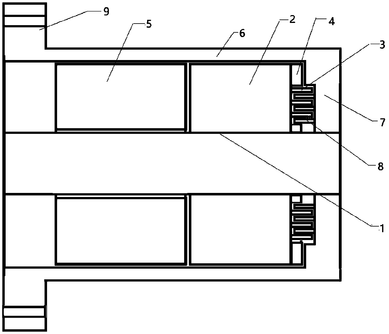
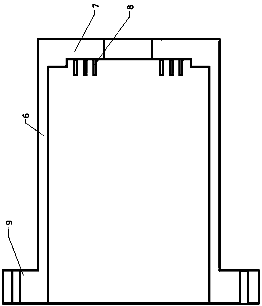
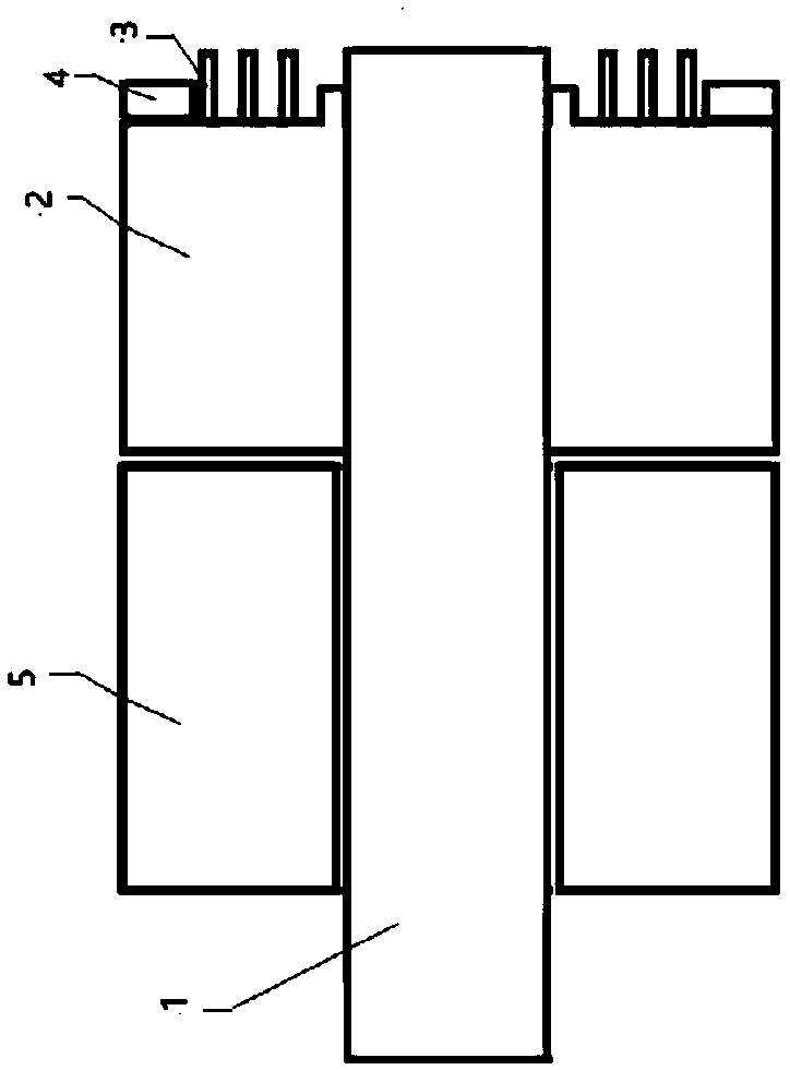
[0018] The combined high-temperature, high-pressure, high-speed sealed bearing is mainly composed of radial labyrinth seals on the end face, thrust bearings (4) and radial bearings (5), which are arranged radially on the outside of the front end face (2) of the T-shaped inner ring (1) A stationary ring (3) and a thrust bearing (4) with ring teeth are arranged, and a radial bearing (5) whose outer diameter is not smaller than the diameter of the front end face (2) is arranged axially on the inner side of the front end face (2); П-shaped outer ring The inner side of the rear end face (7) of (6) is radially provided with a moving ring (8) with annular teeth, and the number of teeth of the moving ring (8) is one more than that of the static ring (3); the T-shaped inner ring (1) and П The outer ring (6) is assembled to form a sealed bearing, and the stationa...


PUM


Abstract

The invention provides a combined type high-temperature high-pressure high-speed seal bearing. The combined type high-temperature high-pressure high-speed seal bearing is mainly composed of an end face radial labyrinth type seal, a thrust bearing and a centripetal bearing. A stationary ring with annular teeth and the thrust bearing are arranged at the outer side of the front end face of a T-shapedinner ring in the radial direction, and the centripetal bearing is arranged in the axial direction. A movable ring with annular teeth is arranged at the inner side of the rear end face of a Greek-letter-pai-shaped outer ring in the radial direction. When the T-shaped inner ring and the Greek-letter-pai-shaped outer ring are assembled, the stationary ring with the annular teeth and the movable ring with the annular teeth are matched to form the end face radial labyrinth type seal. By means of the thrust bearing, axial movement of a shaft is prevented, and the radial labyrinth type seal is stuck. By means of the centripetal bearing, damage, caused by the radial load of the shaft, of the radial labyrinth type seal is eliminated, and a bearing structural form good in seal effect is obtained.The combined type high-temperature high-pressure high-speed seal bearing can be mounted on rotating shafts of a turbine, a compressor, an air blower, a ventilator, a heat separator, an oil pump, a water pump and the like for sealing gas or liquid.

Description

1. Technical field [0001] The invention relates to the field of mechanical equipment, in particular, to a non-contact sealing structure of a rotating shaft. 2. Background technology [0002] The rotary shaft seal is one of the mechanical basic components with precision and complex structure, and is the key component of various pumps, reaction synthesis kettles, turbo compressors, submersible motors and other equipment. Although there are many forms of rotary shaft seals such as gasket seals, packing seals, mechanical seals, and non-contact seals, the labyrinth seal in the non-contact type seal is a number of annular seal teeth arranged in sequence around the shaft. A series of shut-off gaps and expansion cavities are formed between the teeth and the sealed medium will produce a throttling effect when passing through the gaps of the tortuous labyrinth to achieve the purpose of leak prevention. Because there is a gap between the rotor and the casing of the labyrinth seal, the...

Claims


Application Information

Patent Timeline
Patent Type & Authority Applications(China)
IPC IPC(8): F16C21/00F16C33/72
CPCF16C21/00F16C33/72F16C2300/64F16C2300/54F16C2300/22F16C2360/23
Inventor 田原宇乔英云田一良
Owner CHINA UNIV OF PETROLEUM (EAST CHINA)
Why Eureka
Try Eureka