Environmental-friendly chimney device for removing stains of inner wall in manner of heating and circulating water vapor by waste gas afterheat

A heating cycle and smoke exhaust device technology, applied in exhaust gas devices, lighting and heating equipment, indirect heat exchangers, etc., can solve the problems of falling, difficult to clean the inside of the equipment, cumbersome activated carbon replacement process, etc. The effect of reducing waste

Inactive Publication Date: 2019-04-09
黄佩媛
View PDF5 Cites 4 Cited by
  • Summary
  • Abstract
  • Description
  • Claims
  • Application Information

AI Technical Summary

Problems solved by technology

[0002] The current chimney device usually uses electrostatic charge to absorb dust and piles of activated carbon to absorb the flow of air, so as to complete the treatment of gas to achieve the purpose of environmental protection, but in this way It is easy to cause:
[0003] When performing exhaust work, when the piles of activated carbon are used for adsorption, when the flow rate of the airflow is too fast, the internal activated carbon has not completely absorbed the airflow, which will affect the treatment effect, and the activated carbon The replacement process is relatively cumbersome. At the same time, when the internal activated carbon is saturated, the dust inside the airflow is easy to contaminate the equipment under the action of static electricity, and it is difficult to clean the inside of the equipment. At the same time, after the static electricity disappears, the dust will fall inside the equipment. , affecting the next discharge effect

Method used


Image

  • Environmental-friendly chimney device for removing stains of inner wall in manner of heating and circulating water vapor by waste gas afterheat
  • Environmental-friendly chimney device for removing stains of inner wall in manner of heating and circulating water vapor by waste gas afterheat
  • Environmental-friendly chimney device for removing stains of inner wall in manner of heating and circulating water vapor by waste gas afterheat

Examples


Embodiment

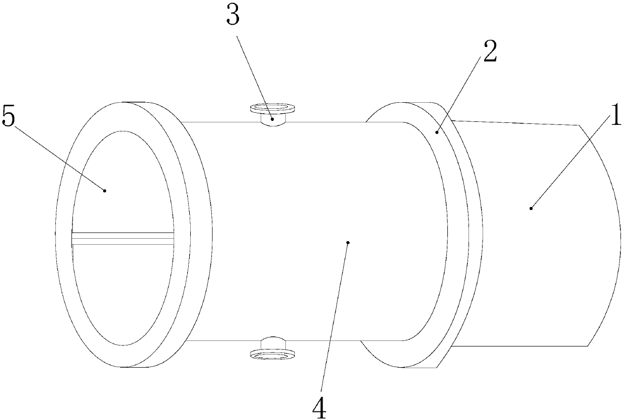
[0025] see figure 1 , the present invention provides an environmentally friendly smoke exhaust pipe device that uses waste heat of exhaust gas to heat circulating water vapor for decontamination of the inner wall. The movable smoke exhaust device 5 is located inside the device housing 4 and is fixedly connected to the device housing 4. The water inlet pipe 3 is arranged on the upper end surface of the device housing 4 and connected through the device housing 4. The junction pipe 1 The right side end face of the movable seat 2 is connected with the movable seat 2 at the same time, the movable seat 2 is arranged on the right side of the device housing 4 and is an integral structure with the device housing 4, and the outer end face of the water inlet pipe 3 is provided A flange with multiple bolt holes for connection.

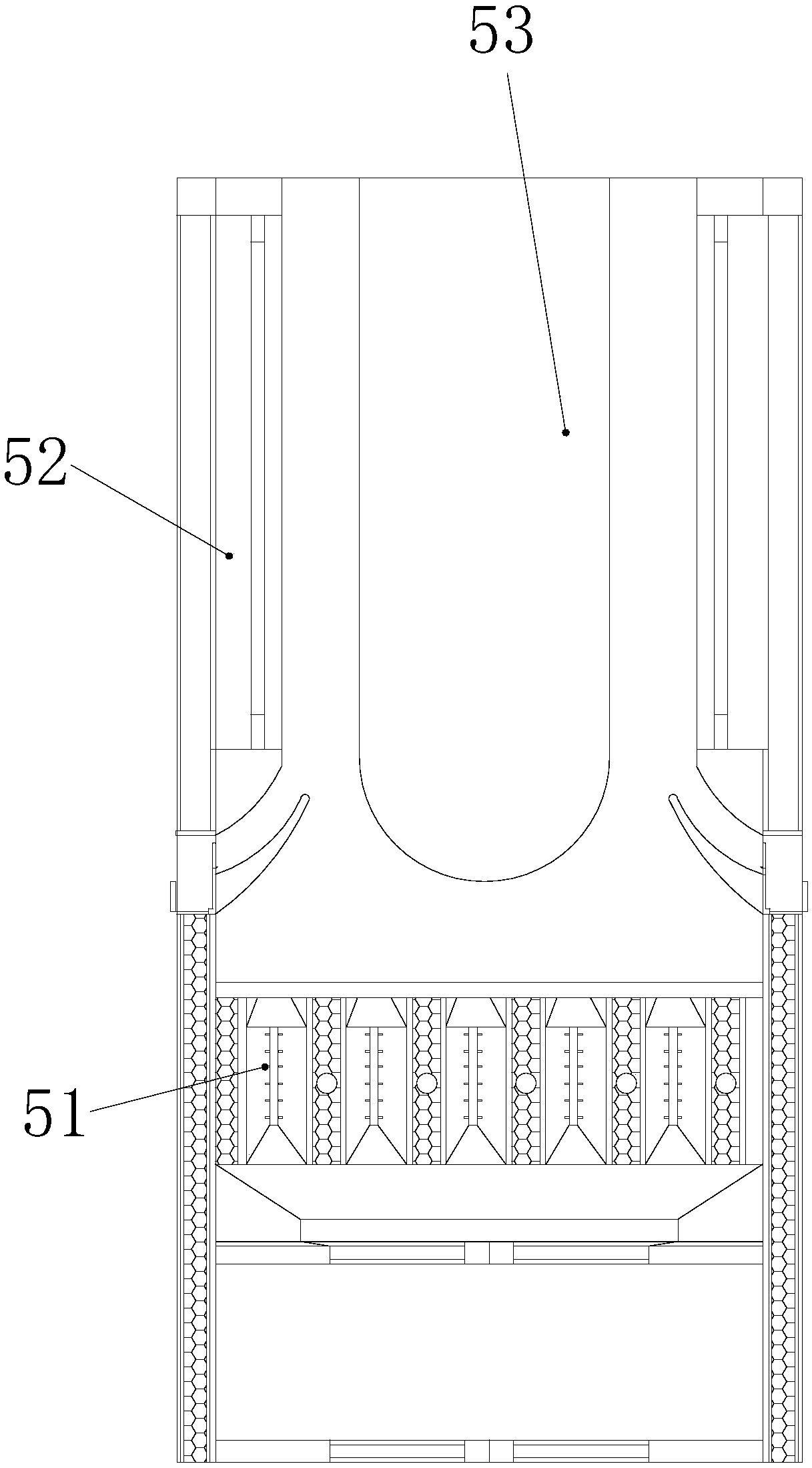
[0026] see figure 2 , the present invention provides an environmentally friendly smoke exhaust device that uses waste heat of exhaust gas to heat circulating ...


PUM


Abstract

The invention discloses an environmental-friendly chimney device for removing stains of an inner wall in a manner of heating and circulating water vapor by waste gas afterheat. The environmental-friendly chimney device structurally comprises a joint pipe, a movable base, a water inlet pipe, a device shell and a movable smoke discharging device, wherein the movable smoke discharging device is positioned in the device shell and is also fixedly connected with the device shell, and water flow formed on a heating rack is heated through afterheat of waste gas, and thus, the produced water vapor is adsorbed on an electrified rack along with the dust, the dust is carried and discharged after condensation is carried out, dust stacked in the device can be prevented, and air flow is separated by using an adsorption rack, and therefore, the inner airflow can be adsorbed by activated carbon preferably, and cleaner gas can be exhausted; through combination of a plurality of equal-size adsorption layers, inner airflow is subjected to subdivision directional output through small hole tubes, and adsorption treatment on a small part of airflow is carried out by using a single adsorption layer; and moreover, the inner activated carbon can be conveniently taken out and replaced in a pushing-embedding mounting way, and the waste of the activated carbon can be reduced.

Description

technical field [0001] The invention relates to the field of waste gas treatment, in particular to an environmentally friendly smoke exhaust pipe device which uses waste heat of waste gas to heat circulating water vapor for decontamination of the inner wall. Background technique [0002] The current chimney device usually uses electrostatic charge to absorb dust and piles of activated carbon to absorb the flow of air, so as to complete the treatment of gas to achieve the purpose of environmental protection, but in this way It is easy to cause: [0003] When performing exhaust work, when the piles of activated carbon are used for adsorption, when the flow rate of the airflow is too fast, the internal activated carbon has not completely absorbed the airflow, which will affect the treatment effect, and the activated carbon The replacement process is relatively cumbersome. At the same time, when the internal activated carbon is saturated, the dust inside the airflow is easy to ...

Claims


Application Information

Patent Timeline
Patent Type & Authority Applications(China)
IPC IPC(8): F23J11/00F23J13/00B01D53/04B03C3/28F28D7/16
Inventor 黄佩媛
Owner 黄佩媛
Why Eureka
Try Eureka