Mutual-impacting-type chemical raw material stirring and mixing device

A chemical raw material, stirring and mixing technology, which is applied to mixers with rotating stirring devices, mixers, mixer accessories, etc., can solve problems such as poor mixing effects, and achieve the effects of convenient operation, simple structure, and strong practicability

Inactive Publication Date: 2019-04-12
张磊
View PDF8 Cites 15 Cited by
  • Summary
  • Abstract
  • Description
  • Claims
  • Application Information

AI Technical Summary

Problems solved by technology

However, the stirring mechanism of the existing chemical raw material mixing equipment generally stirs the chemical raw mate

Method used


Image

  • Mutual-impacting-type chemical raw material stirring and mixing device
  • Mutual-impacting-type chemical raw material stirring and mixing device
  • Mutual-impacting-type chemical raw material stirring and mixing device

Examples


Embodiment 1

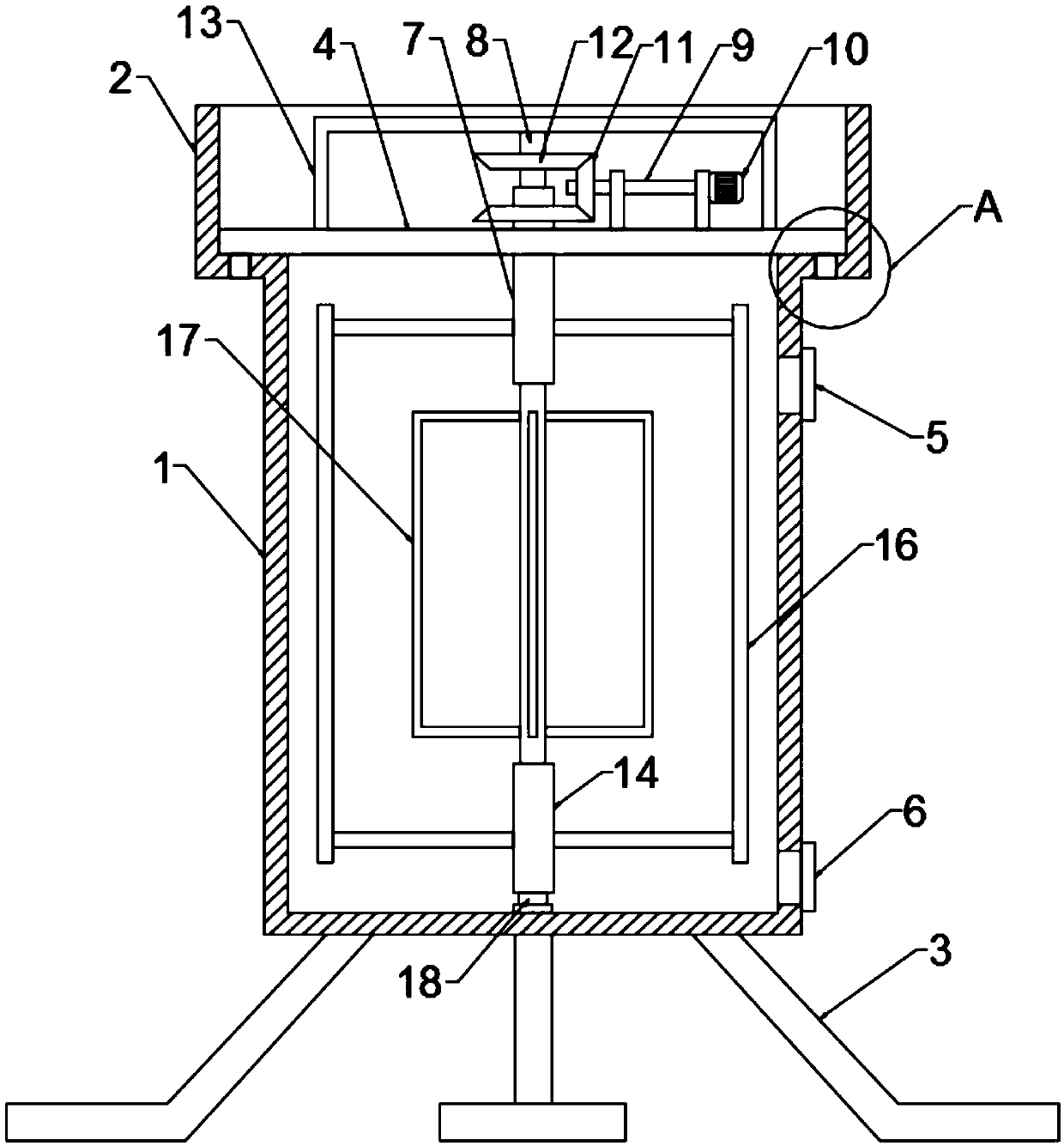
[0021] see Figure 1~4 , in an embodiment of the present invention, a mutual impact type chemical raw material stirring and mixing device includes a mixing cylinder 1 and a placement port 2 connected to the upper end of the mixing cylinder 1 as a whole, and the size of the placement port 2 is larger than that of the mixing cylinder. The top port of the cylinder body 1, the installation cover 4 is installed inside the placement port 2, and the bottom wall edge of the installation cover 4 is connected with the bottom wall of the placement port 2 through a limited clamping mechanism. A plurality of defined protrusions 29 on the bottom wall of the board 4 and a plurality of defined through grooves 28 arranged on the bottom wall of the placement port 2, the defined protrusions 29 correspond to the defined through grooves 28 one by one and the defined protrusions 29 are inserted into the The inner side of the through groove 28 is limited, and then the degree of freedom of rotation o...

Embodiment 2

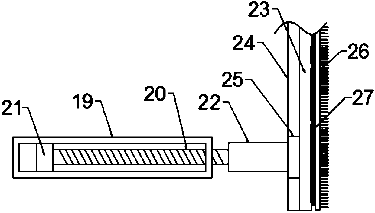
[0025] The difference between this embodiment and Embodiment 1 is that the first stirring rod frame 16 is an assembled structure, which includes two sleeves fixedly connected to the side walls of the first rotating sleeve 7 and the second rotating sleeve 14 respectively. The pipe 19 and the outer ends of the two casing pipes 19 are connected with the same vertical lever 23 through the adjustment mechanism, and the side wall of the vertical lever 23 is provided with a sliding card slot 24, and the inner side of the sliding card slot 24 is provided with a connection for sliding connection therewith. The slider 25, the connecting slider 25 is connected to the outer end of the sleeve 19, and the side wall of the vertical lever 23 away from the sleeve 19 is connected with a cleaning device for cleaning the inner wall of the mixing cylinder 1 through a Velcro 27. Brush 26, the adjustment mechanism includes a screw rod 20 inserted through the inside of the sleeve 19 and screwed with t...


PUM


Abstract

The invention discloses a mutual-impacting-type chemical raw material stirring and mixing device, and belongs to the technical field of chemical equipment. The chemical raw material stirring and mixing device comprises a mixing cylinder and a placement port which is integrally connected with the upper end of the mixing cylinder, a mounting cover plate is mounted at the inner side of the placementport, a vertical first rotary casing pipe is rotatably mounted in the center of the mounting cover plate, and a rotary rod shaft which is rotatably connected with the first rotary casing pipe througha bearing penetrates into the first rotary casing pipe; a second rotary casing pipe is rotatably connected to the bottom of the rotary rod shaft, multiple first stirring rod shelves which are annularly arranged around the center axis of the first rotary casing pipe are arranged at the outer side of the first rotary casing pipe, multiple second stirring rod shelves are arranged on the outer side wall of the rotary rod shaft, a power mechanism for driving the first rotary casing pipe and the rotary rod shaft to rotate in opposite directions is arranged at the upper end of the mounting cover plate, and a rod lifting shelf is arranged at the top of the mounting cover plate. The chemical raw material stirring and mixing device is simple in structure and convenient to operate, and chemical raw materials are conveniently mixed uniformly; meanwhile, a stirring part is convenient to detach and maintain, and the practicability is high.

Description

technical field [0001] The invention relates to the technical field of chemical equipment, in particular to a mutual impact stirring and mixing device for chemical raw materials. Background technique [0002] Chemical raw materials can generally be divided into two categories: organic chemical raw materials and inorganic chemical raw materials. Organic chemical raw materials can be divided into alkanes and their derivatives, olefins and their derivatives, alkynes and their derivatives, quinones, aldehydes, alcohols, Ketones, phenols, ethers, anhydrides, esters, organic acids, carboxylates, carbohydrates, heterocycles, nitriles, halogenated amidamides and others; the main raw materials of inorganic chemical products are Sulfur, sodium, phosphorus, potassium, calcium and other chemical minerals and coal, oil, natural gas, air, water, etc. In addition, by-products and wastes of many industrial sectors are also raw materials for inorganic chemicals. [0003] Chemical machinery ...

Claims


Application Information

Patent Timeline
IPC IPC(8): B01F7/32B01F15/00B01F27/96
CPCB01F27/054B01F27/092B01F27/091B01F27/96B01F35/121
Inventor 张磊
Owner 张磊
Why Eureka
Try Eureka