
Planer device for clearing part surfaces and using method of planer device

A technology of parts and planers, which is applied in the field of aero-engine manufacturing, can solve the problems of difficult control of operation accuracy, long cutting time, and low production efficiency, and achieve the effects of easy control of operation accuracy, short cutting time, and high production efficiency

Inactive Publication Date: 2019-04-12
CHINA HANGFA GUIZHOU LIYANG AVIATION POWER CO LTD
View PDF6 Cites 0 Cited by
  • Summary
  • Abstract
  • Description
  • Claims
  • Application Information

AI Technical Summary

Problems solved by technology

In the absence of special means, the only way to remove Teflon residues is to use a blade to shovel and cut bit by bit, but this method will make it difficult to control the accuracy of the operation, easily scratch the parts, and cause the parts to be scrapped
And the cutting time is long, the production efficiency is low
In short, the cost of this production method is difficult to control, so it is necessary to find a new alternative operation method to solve the current predicament

Method used


Image

  • Planer device for clearing part surfaces and using method of planer device
  • Planer device for clearing part surfaces and using method of planer device
  • Planer device for clearing part surfaces and using method of planer device

Examples


Embodiment Construction

[0029] The technical solution of the present invention is further described below, but the scope of protection is not limited to the above.

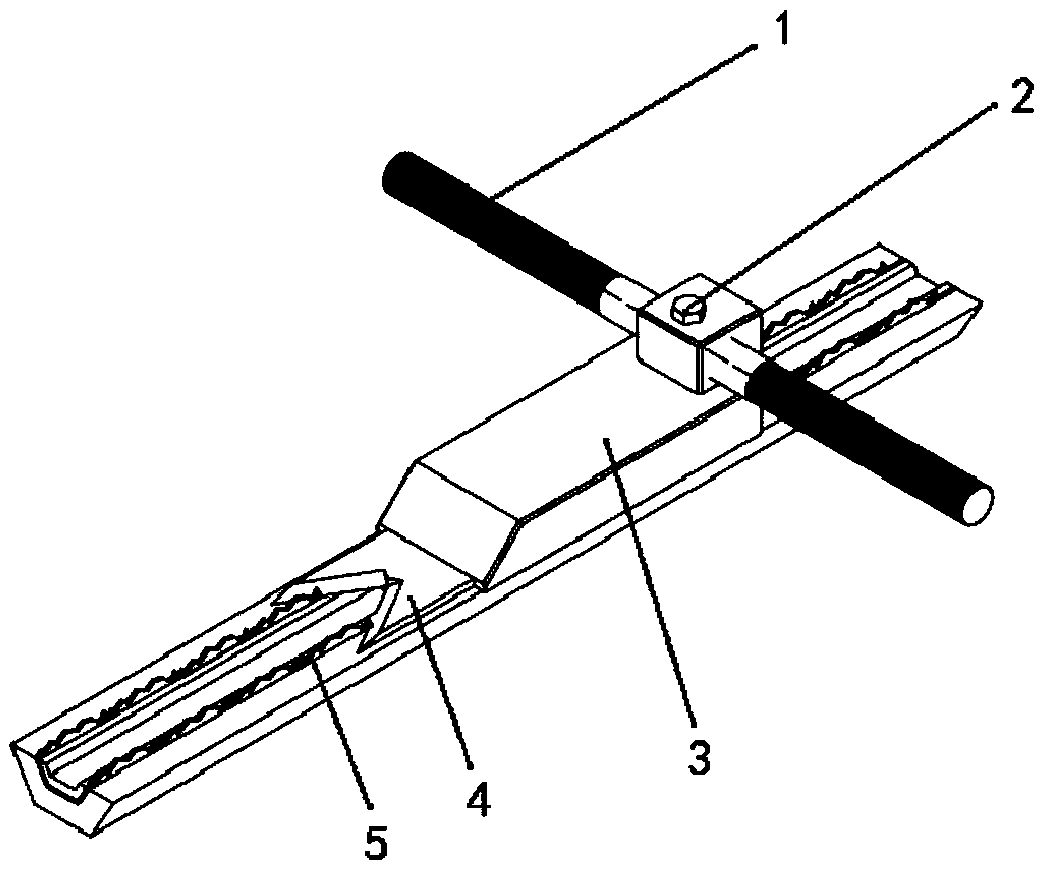
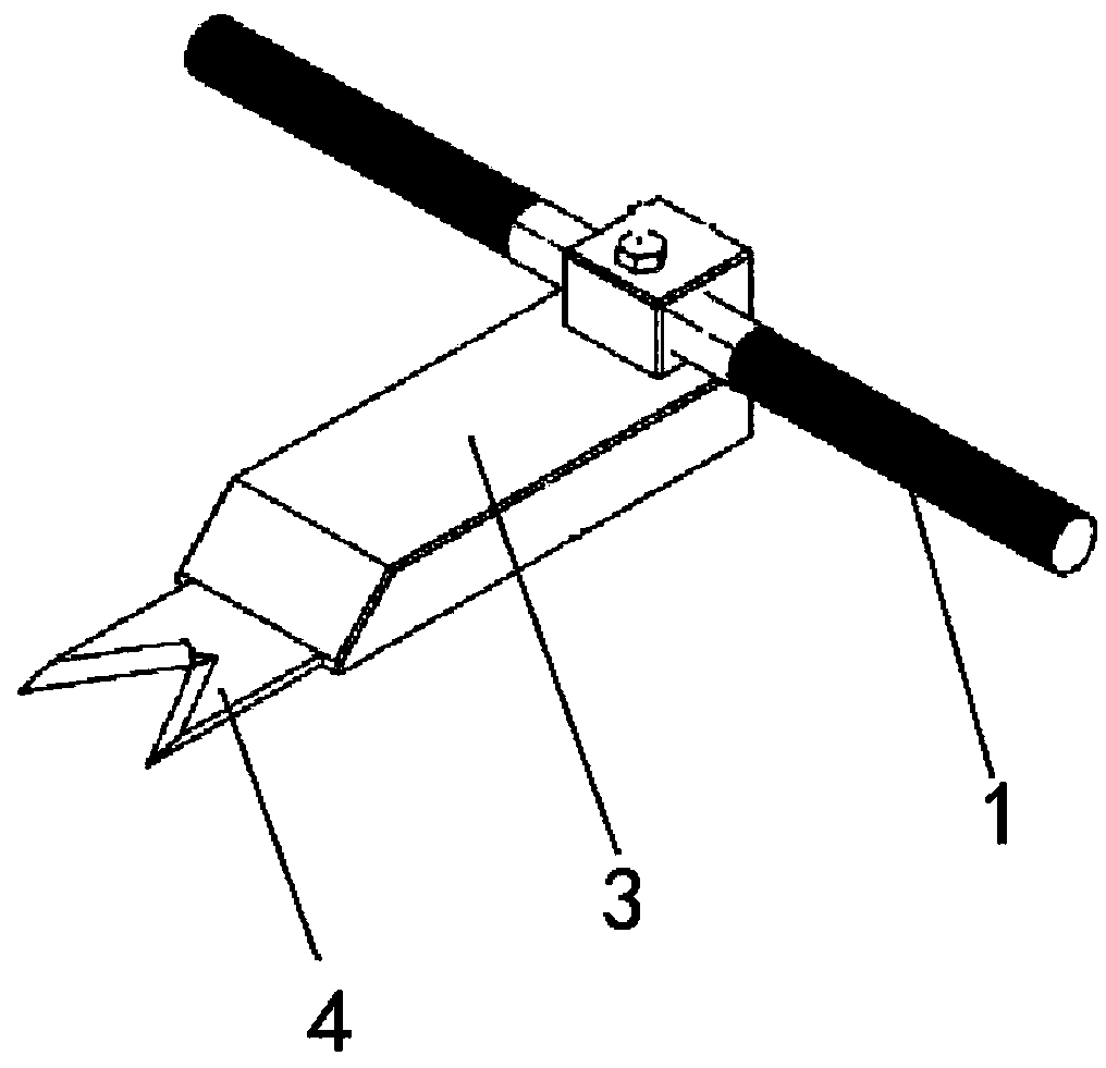
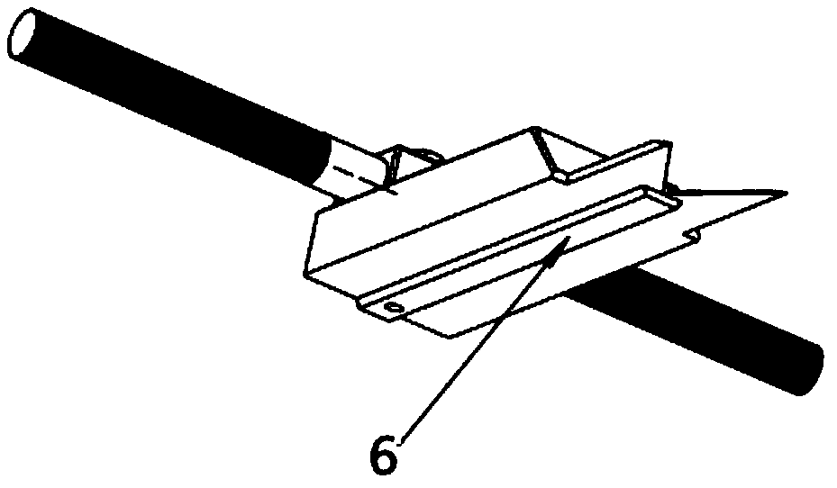
[0030] Such as Figure 1-7 As shown, the present invention provides a planer device for removing the surface of parts, including a handle 1, a connecting block 8, a base 3 and a planer 4; the handle 1 is mounted on the connecting block 8; the connecting block 8 Installed on the base 3 through the fixing member 2; the planer 4 is installed at the top position below the base 3; the base 3 is provided with a convex strip 6; the connecting block 8 is provided with a convex block 7 and a concave Hole A9, and there is a gap between the two; the base 3 is provided with a square groove 11 and a concave hole B10, and there is a gap between the two; the convex block 7 is connected with the square groove 11; the concave hole The positions of A9 and the concave hole B10 correspond to the same.

[0031] The fixing member 2 is fixed by bolts.

[0032] A c...


PUM


Abstract

The invention provides a planer device for clearing the part surfaces and a using method of the planer device. The planer device comprises a grip handle, a connecting block, a base and a planer tool;the grip handle is installed on the connecting block; the connecting block is installed on the base through a fixing piece; the planer tool is installed at the top end of the lower part of the base; aconvex strip is arranged on the lower part of the base; the connecting block is provided with a convex block and a concave hole A, and a gap is formed between the convex block and the concave hole A;the base is provided with a square groove and a concave hole B, and a gap is formed between the square groove and the concave hole B; the convex block is connected with the square groove; and the concave hole A and the concave hole B are the same correspondingly. The operation accuracy of the planer device is easy to control, parts can be protected against scratches, the part scrapping probability is decreased, the cutting time is short, and the production efficiency is high.

Description

Technical field [0001] The invention belongs to the technical field of aeroengine manufacturing, and specifically relates to a planer device for removing the surface of a part and a method of use thereof. Background technique [0002] For the structure of the guideway cover of aeroengine parts, after the processing of its various dimensions and parameters, it is required that the outer U surface of the guideway cover of the part needs to be bonded with a layer of Teflon material. The bonding processing principle of Teflon material is to cut the Teflon material according to the corresponding size of the part guide rail cover and glue them together. Secondly, the fixture base, the Teflon material and the parts guide cover plate, which have been bonded into one body and the fixture top cover, are superimposed and fixed together. Then put them in a drying furnace for high temperature curing. Due to high temperature and clamp extrusion, the Teflon will overflow the residue on the upp...

Claims


Application Information

Patent Timeline
Patent Type & Authority Applications(China)
IPC IPC(8): B23D9/00
CPCB23D9/00
Inventor 颜明华张世波
Owner CHINA HANGFA GUIZHOU LIYANG AVIATION POWER CO LTD
Learn More