Picosecond pulse laser welding machine

A laser welding machine and picosecond pulse technology, applied in the field of picosecond pulse laser welding machine, can solve the problems of easy brittleness of materials, weak welding, long laser pulse heating time, etc., and achieve high connection strength, high pulse peak value, The effect of high welding strength

Pending Publication Date: 2019-04-12
苏州镭扬激光科技有限公司
View PDF9 Cites 1 Cited by
  • Summary
  • Abstract
  • Description
  • Claims
  • Application Information

AI Technical Summary

Problems solved by technology

[0002] When the laser welding machine is doing laser welding of the same material or different materials, due to the long heating time of the laser pulse, the material to be welded is likely to become brittle in many cases. The longer the heating time, the easier the material becomes brittle, especially for When welding between different materials, because the oxides between different metals are generally brittle, the welding is not strong

Method used


Image

  • Picosecond pulse laser welding machine
  • Picosecond pulse laser welding machine
  • Picosecond pulse laser welding machine

Examples


Embodiment Construction

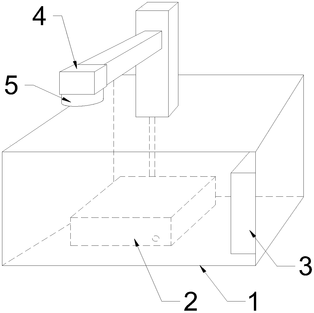
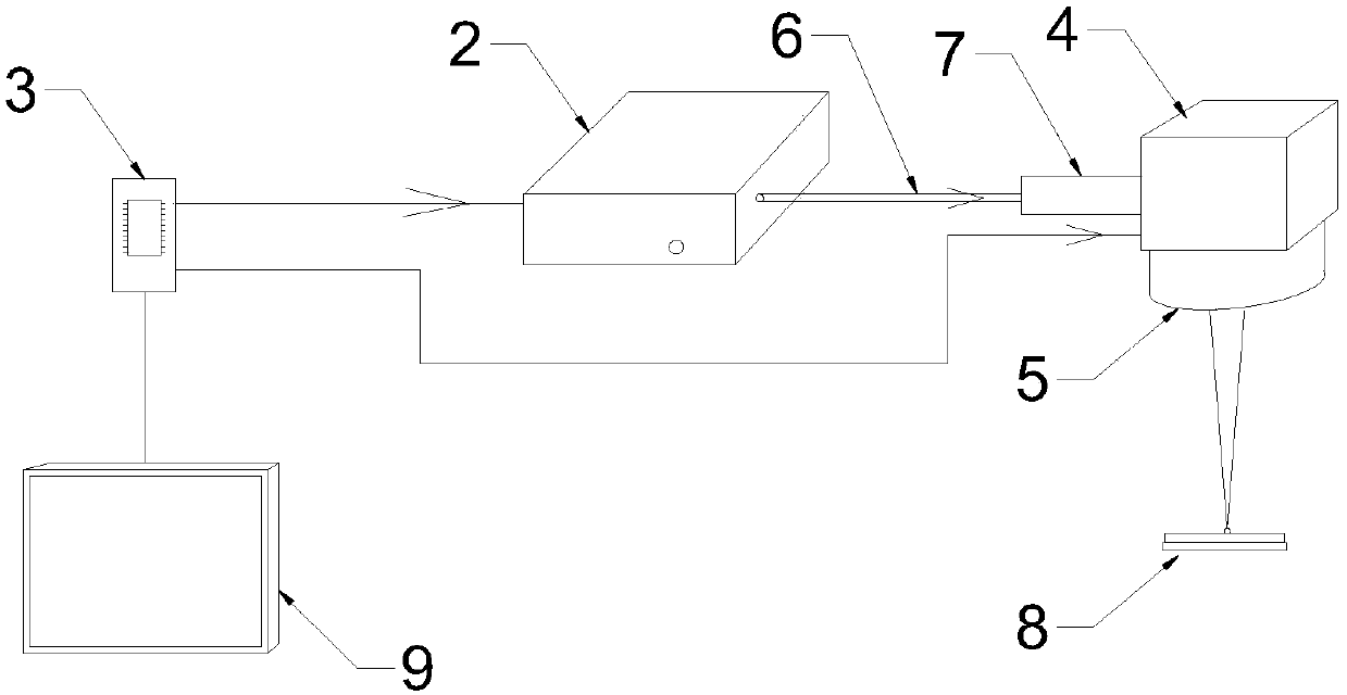
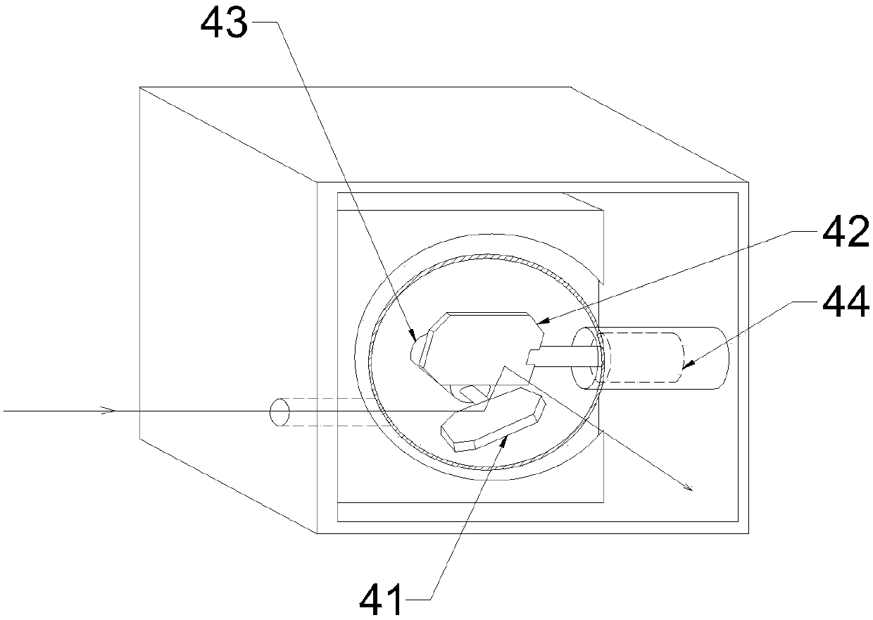
[0021] Such as Figure 1 to Figure 3 As shown, a picosecond pulse laser welding machine includes a chassis 1. A picosecond pulse laser 2 and a control board 3 are arranged in the chassis 1. A vibrating mirror 4 and a field mirror 5 are sequentially installed on the top of the chassis 1 through a bracket. The field mirror 5 is connected to the bottom of the vibrating mirror 4. The picosecond pulse laser 2 is connected to the vibrating mirror 4 through the optical fiber 6. The vibrating mirror 4 includes an X-axis mirror 41 and a Y-axis mirror 42. The X-axis mirror 41 is connected to an X-axis motor 43, and the X-axis motor 43 can drive the X-axis mirror 41 to vibrate and rotate at high speed, and the Y-axis mirror 42 is connected with a Y-axis motor 44, which can drive the Y-axis mirror 42 to vibrate and rotate at a high speed; the laser beam emitted by the picosecond pulse laser 2 passes through the X After the axis lens 41 and the Y axis lens 42 change direction and vibrate a...


PUM

PropertyMeasurementUnit
diameteraaaaaaaaaa
thicknessaaaaaaaaaa
wavelengthaaaaaaaaaa

Abstract

The invention provides a picosecond pulse laser welding machine which comprises a machine box. A picosecond pulse laser device and a control board card are arranged in the machine box, a galvanometerand a field lens are sequentially arranged above the machine box through a support, the field lens is connected to the bottom of the galvanometer, the picosecond pulse laser device is connected with the galvanometer through an optical fiber, the galvanometer comprises an X-axis lens and a Y-axis lens, the X-axis lens is connected with an X-axis motor, the Y-axis lens is connected with a Y-axis motor, a laser beam emitted by the picosecond pulse laser device sequentially passes through the X-axis lens, the Y-axis lens and the field lens to be focused on a workpiece to be welded, the signal output end of the control board card is respectively connected to the picosecond pulse laser device, the X-axis motor and the Y-axis motor, and the motion trajectory of the laser beam on the workpiece isa spiral trajectory. High-speed welding can be carried out on the workpiece to form fine welding spots in the spiral trajectory, and the tens of thousands of welding spots are arranged into a spiral welding pattern. When the welding machine is used for welding, two metal materials are not likely to be embrittled, and the welding strength is high.

Description

technical field [0001] The invention belongs to the technical field of laser welding, and in particular relates to a picosecond pulse laser welding machine. Background technique [0002] When the laser welding machine is doing laser welding of the same material or different materials, due to the long heating time of the laser pulse, the material to be welded is likely to become brittle in many cases. The longer the heating time, the easier the material becomes brittle, especially for When welding between different materials, because the oxides between different metals are generally brittle, the welding is not strong. Contents of the invention [0003] The object of the present invention is to provide a picosecond pulse laser welding machine, the material heated by the laser is not easy to embrittle, and the welding strength is high. [0004] The present invention provides following technical scheme: [0005] A picosecond pulse laser welding machine, including a chassis, ...

Claims


Application Information

Patent Timeline
Patent Type & Authority Applications(China)
IPC IPC(8): B23K26/22B23K26/082
CPCB23K26/22B23K26/082
Inventor 戴家文
Owner 苏州镭扬激光科技有限公司
Why Eureka
Try Eureka