Central locating mechanism and device

A technology of center positioning and power mechanism, which is applied in the direction of workpiece clamping devices and manufacturing tools, can solve the problems that the center position accuracy cannot meet the test requirements and the substrate size tolerance is large, so as to improve repeatability accuracy, ensure stability and reliability sexual effect

Pending Publication Date: 2019-04-12
SHENZHEN JPT OPTO ELECTRONICS CO LTD
View PDF0 Cites 7 Cited by
  • Summary
  • Abstract
  • Description
  • Claims
  • Application Information

AI Technical Summary

Problems solved by technology

[0003] In order to improve the accuracy of the center position of tiny components, a common method is to design a side positioning mechanism on the fixture. However, due to

Method used


Image

  • Central locating mechanism and device
  • Central locating mechanism and device
  • Central locating mechanism and device

Examples


Example Embodiment

[0039] Example one:

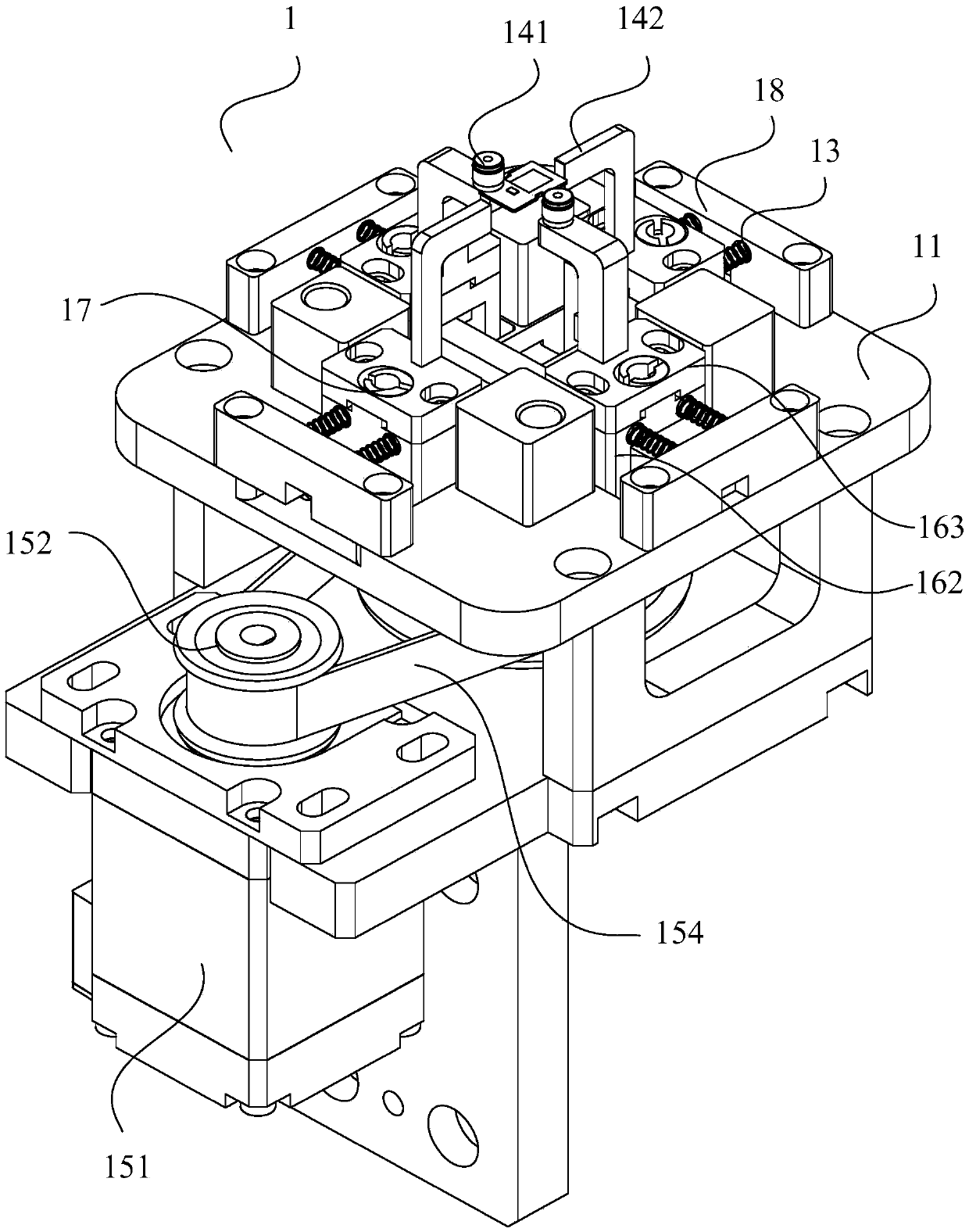
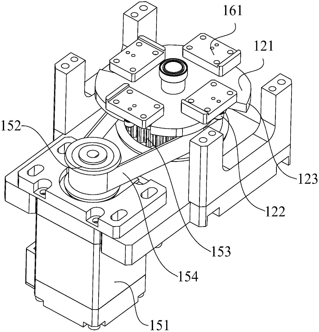
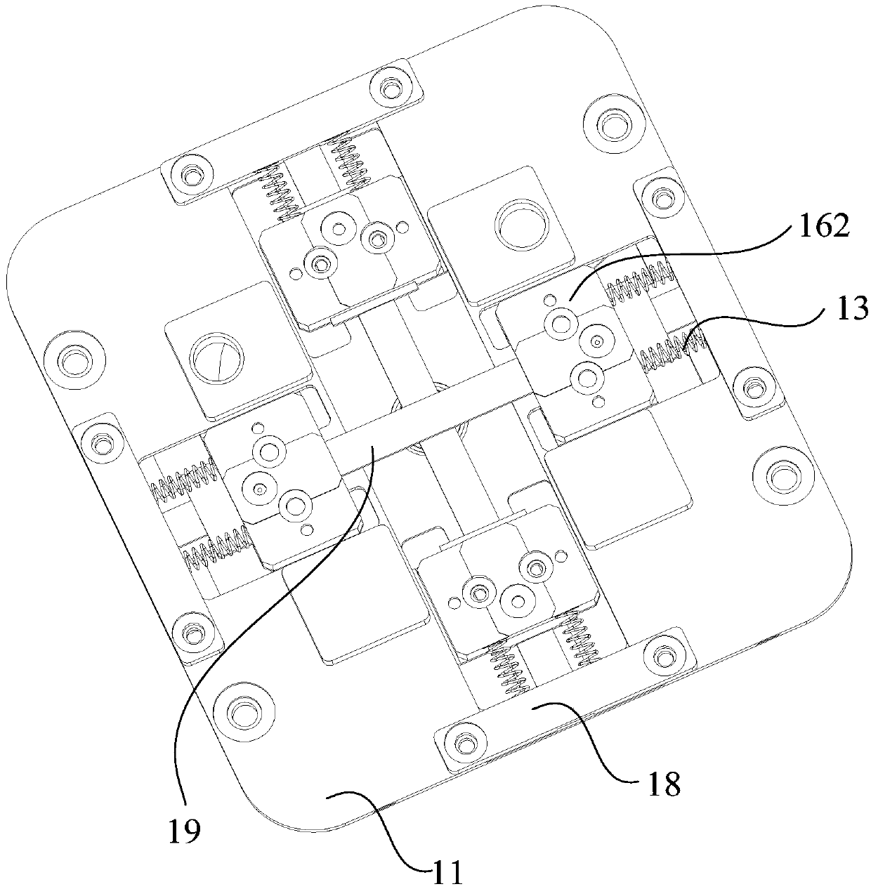
[0040] Such as figure 1 , figure 2 , image 3 , Figure 4 As shown, figure 1 Shows a schematic structural diagram of a center positioning mechanism provided by an embodiment of the present application; figure 2 Shows a first partial schematic diagram of a center positioning mechanism provided by an embodiment of the present application; image 3 Shows a second partial schematic diagram of the center positioning mechanism provided by the embodiment of the present application; Figure 4 The schematic diagram of the structure of the base provided by the embodiment of the present application is shown.

[0041] A center positioning mechanism 1, including: a power mechanism, a cam mechanism, a base 11, an elastic member 13, and a clamping part;

[0042] The cam mechanism includes a cam 121 and at least two followers arranged opposite to the outer edge of the cam 121, and the output end of the power mechanism is drivingly connected with the rotating shaft of the cam 1...

Example Embodiment

[0077] Embodiment two:

[0078] Based on the same technical concept, an embodiment of the present application also provides a center positioning device, such as Figure 5 As shown, Figure 5 It shows a partial schematic diagram of the center positioning device provided by the embodiment of the present application.

[0079] A center positioning device, including a lifting mechanism 2 and a center positioning mechanism 1;

[0080] The lifting mechanism 2 is connected to the center positioning mechanism 1 for adjusting the level of the clamping part of the center positioning mechanism 1.

[0081] Specifically, the lifting mechanism 2 is used to lift the entire center positioning mechanism 1 so that the clamping part is located at the height of the corresponding plane of the VCSEL module. In the implementation of this application, the lifting mechanism 2 uses a lifting cylinder. It should be noted that the lifting mechanism 2 may also be a hydraulic cylinder, an electric push rod, etc.,...


PUM


Abstract

The invention provides a central locating mechanism and device, and relates to the technical field of locating of micro parts. The central locating mechanism comprises a power mechanism, a cam mechanism, a base, elastic parts and clamping parts, wherein the cam mechanism comprises a cam and at least two driven parts oppositely arranged on the edge of the outer side of the cam; an output end of thepower mechanism is in transmission connection with a rotating shaft of the cam; the base is erected above the cam; at least two oppositely arranged connecting seats are arranged on the base; each connecting seat is connected with one driven part; the clamping parts which extend in the direction away from the base are arranged on the connecting seats; the elastic parts are arranged on the connecting seats; and the driven parts abut the edge of the outer side of the cam under the action of the elastic parts, and the clamping parts move towards the center to clamp a to-be-detected product. According to the central locating mechanism, precision of a central position of the to-be-detected product can be improved, and stability and reliability of testing data acquisition are guaranteed.

Description

technical field [0001] The present application relates to the technical field of positioning of tiny parts, in particular to a center positioning mechanism and equipment. Background technique [0002] In the process of optical testing of micro components, whether the selection of positioning reference is reasonable or not determines the accuracy of the center position of micro components, and the accuracy of the center position of micro components affects the stability and reliability of test data collection. [0003] In order to improve the accuracy of the center position of tiny components, a common method is to design a side positioning mechanism on the fixture. However, due to the large size tolerance of the substrate of tiny components, the center position accuracy produced by the side positioning method still cannot meet the test requirements. . Contents of the invention [0004] In view of this, the purpose of the present application is to provide a center position...

Claims


Application Information

Patent Timeline
IPC IPC(8): B25B11/00
CPCB25B11/00
Inventor 许根夫李喆
Owner SHENZHEN JPT OPTO ELECTRONICS CO LTD
Why Eureka
Try Eureka