Non-rigid connection rapid-drive high-precision displacement measuring device

A displacement measurement, non-rigid technology, applied in the direction of measuring devices, instruments, etc., can solve the problems of measuring rod parallelism error, affecting measurement accuracy, no degree of freedom, etc., to improve repeatability accuracy, improve measurement accuracy, and improve measurement efficiency Effect

Pending Publication Date: 2019-10-01
CHENGDU HUALIANG SENSOR CO LTD
View PDF0 Cites 0 Cited by
  • Summary
  • Abstract
  • Description
  • Claims
  • Application Information

AI Technical Summary

Problems solved by technology

[0003] 1. Ordinary micrometers use a ratchet device. The force measurement is relatively stable when the ratchet device is at a constant speed, but the rotation speed of the ratchet is easily affected by external factors and fluctuates. low repeatability
The force of the lever micrometer is relatively stable, but it is limited to a very small stroke range. In order to achieve high-precision measurement, the lever micrometer needs to use a standard gauge block for zero adjustment before measurement, that is, relative measurement. The measurement process is more complicated. , while ordinary micrometers use absolute measurement, the measurement process is relatively simple
[0004] 2. The measuring shaft and the driving structure of the traditional measuring tool are rigidly linked. There must be a gap in the driving part to move. This gap will transfer the external force of the measuring tool to the measuring shaft from the rigid connection, so the measuring rod will be skewed after being subjected to lateral force. As a result, the original parallel accuracy between the measuring rod and the measuring anvil is lost, resulting in a parallelism error, which affects the measurement accuracy. The axial force causes the measurement force to be unstable, which also affects the measurement accuracy;
[0005] 3. Ordinary micrometers adopt a screw-in structure, which will cause scratches on the surface of the measured part and damage the measured part, and the measuring rod will produce parallelism errors after being subjected to lateral forces, which will affect the measurement accuracy. The rod and the threaded pipe are threaded, so that the measuring rod and the threaded pipe will be fixed to each other when they are not rotating, and there is no degree of freedom in the axial direction. During manual operation, if the threaded pipe is rotated too fast, the measuring rod and the probe will Collision with the part to be tested will damage the part to be tested, and the collision will also slightly deform the surface of the part to be tested, which will no longer be the original size, which will affect the measurement accuracy. Deformation will also affect the measurement accuracy. The caliper adopts the gear type, which overcomes the defects of the rotary micrometer. However, because the caliper is usually geared, the force on the measuring rod is also not constant, and repeatability errors are prone to occur;
[0006] 4. In the measurement of large batches and large ranges, it is necessary to manually rotate the threaded tube to make the probe and anvil suitable for parts of different sizes and different ranges. The range switching cycle is long, the measurement efficiency is low, and the operation of the measurement personnel is time-consuming and laborious.

Method used


Image

  • Non-rigid connection rapid-drive high-precision displacement measuring device
  • Non-rigid connection rapid-drive high-precision displacement measuring device
  • Non-rigid connection rapid-drive high-precision displacement measuring device

Examples


Embodiment Construction

[0030] The technical solutions of the present invention will be clearly and completely described below in conjunction with the embodiments. Apparently, the described embodiments are only some of the embodiments of the present invention, not all of them. Based on the embodiments of the present invention, all other embodiments obtained by those skilled in the art without making creative efforts belong to the protection scope of the present invention.

[0031] refer to Figure 1-5 , the present invention provides a technical solution:

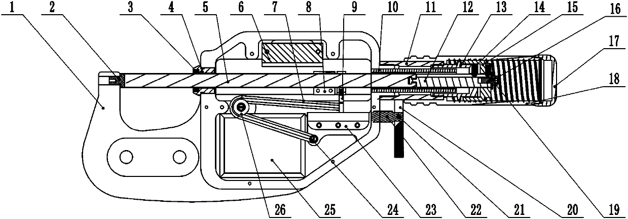
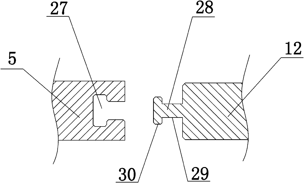
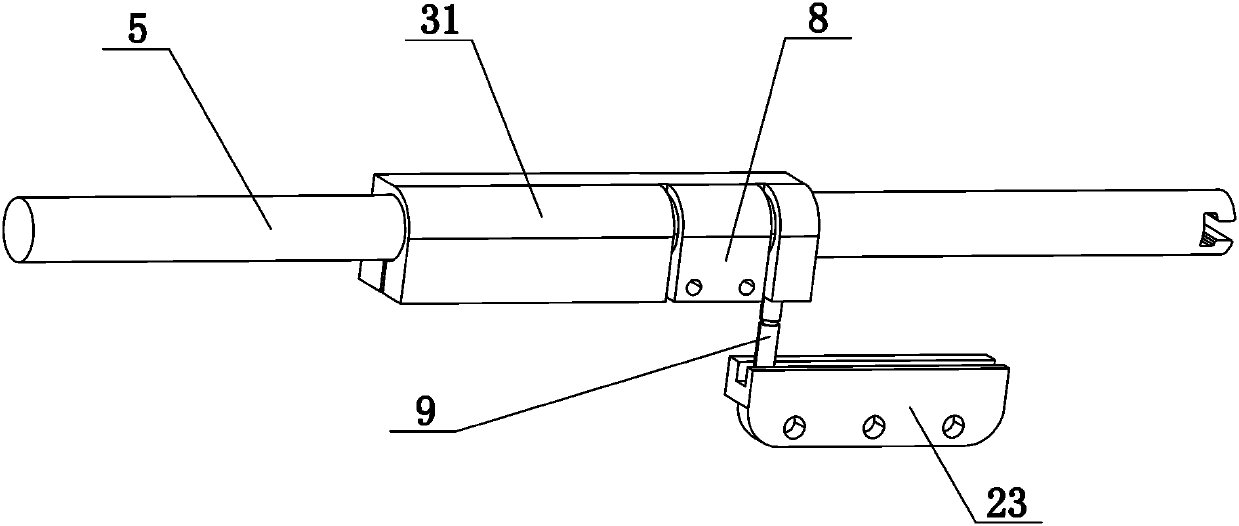
[0032] A non-rigidly connected fast-drive high-precision displacement measuring device, including a bracket 1, a threaded pipe 18, a threaded column 15, and an anvil 2. The bracket 1 is provided with a measuring shaft, an elastic element, and a measuring element for measuring the displacement of the measuring shaft , the internal threads of the threaded pipe 18 cooperate with the external threads of the threaded column 15 . Described support 1 i...


PUM


Abstract

The invention discloses a non-rigid connection rapid-drive high-precision displacement measuring device comprising a support, a threaded pipe, a threaded column, and a measuring anvil; internal threads of the threaded pipe are matched with external threads of the threaded column, a measuring shaft, an elastic element and a measuring element used for measuring the displacement of the measuring shaft are arranged in the support, one end of the measuring shaft is a measuring head, the measuring head is matched with the measuring anvil, the measuring shaft is connected with the threaded column, the threaded column only has the degree of freedom in the axial direction under the action of a guiding mechanism, the measuring shaft is connected with the support through a linear guide rail, one endof the elastic element is connected with the support, the other end of the elastic element is connected with the measuring shaft, and the elastic element is used for exerting restoring force towards the direction of a measured point on the measuring shaft. According to the non-rigid connection rapid-drive high-precision displacement measuring device in the invention, the measuring shaft and the driving structure are connected in a non-rigid mode, the measuring rod only provides constant measuring force at the same deformation position by a spring, thereby improving the repeatability precisionand preventing too large external force from acting on the measuring rod to affect the precision of the measuring tool and damage the measured piece, a rotating and stirring mode is adopted, the requirement for fast switching size is met, and the measuring efficiency is high.

Description

technical field [0001] The invention relates to a displacement measuring device, in particular to a non-rigidly connected fast-driving high-precision displacement measuring device. Background technique [0002] Displacement measuring devices, such as micrometers, can be used to measure length to an accuracy of 0.01mm. Existing micrometers have the following disadvantages: [0003] 1. Ordinary micrometers use a ratchet device. The force measurement is relatively stable when the ratchet device is at a constant speed, but the rotation speed of the ratchet is easily affected by external factors and fluctuates. The repeatability accuracy is low. The force of the lever micrometer is relatively stable, but it is limited to a very small stroke range. In order to achieve high-precision measurement, the lever micrometer needs to use a standard gauge block for zero adjustment before measurement, that is, relative measurement. The measurement process is more complicated. , while ordi...

Claims


Application Information

Patent Timeline
Patent Type & Authority Applications(China)
IPC IPC(8): G01B21/02
CPCG01B21/02
Inventor 杜军黄郑平
Owner CHENGDU HUALIANG SENSOR CO LTD
Why Eureka
Try Eureka