Ocean buoy

A buoy and ocean technology, applied in buoys, special-purpose ships, anti-collision and other directions, can solve the problems of drift of the center of gravity of the buoy, deformation of the floating body, and the breaking of the anchor chain, so as to reduce the instantaneous impact force and avoid deformation due to force. , the effect of increasing the buffer stroke

Active Publication Date: 2019-04-12
THE FIRST INST OF OCEANOGRAPHY SOA
View PDF5 Cites 2 Cited by
  • Summary
  • Abstract
  • Description
  • Claims
  • Application Information

AI Technical Summary

Problems solved by technology

[0003] 1. The existing marine buoys prevent ship collision by installing rubber rings, and the anti-collision effect is poor. When a sailing ship collides with marine buoys, the instantaneous impact force on the floating body is far greater than the buffer limit of the rubber ring, causing the floating body to deform under force. The center of gravity of the buoy is shifted, and the force is uneven when floating on the sea surface, and it is easy to capsize in the waves, resulting in damage to the ocean buoy, unable to continue to collect marine hydrology, water quality and meteorological data, endangering the safety of relevant personnel and related facilities
[0004] 2. The floating body moves in the flowing seawater and pulls the anchor chain, making the anchor chain tight. When a ship hits the buoy along the direction of seawater flow, the floating body is hit by a strong impact, and the anchor chain is easily broken. Disconnected from the anchor chain and drifting with the flowing sea water, resulting in the loss of marine buoys, the maritime department cannot continue to obtain marine hydrology, water quality and meteorological data in the corresponding sea area, endangering the safety of relevant personnel and related facilities

Method used


Image

  • Ocean buoy
  • Ocean buoy
  • Ocean buoy

Examples


Embodiment Construction

[0025] The following will clearly and completely describe the technical solutions in the embodiments of the present invention with reference to the accompanying drawings in the embodiments of the present invention. Obviously, the described embodiments are only some, not all, embodiments of the present invention. Based on the embodiments of the present invention, all other embodiments obtained by persons of ordinary skill in the art without making creative efforts belong to the protection scope of the present invention.

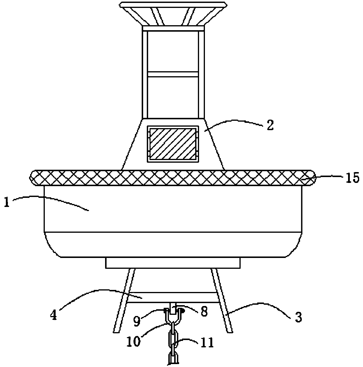
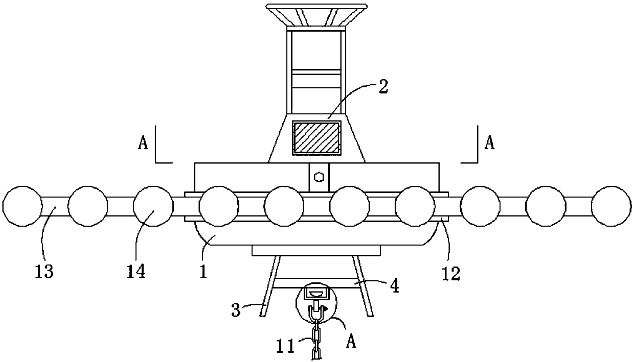
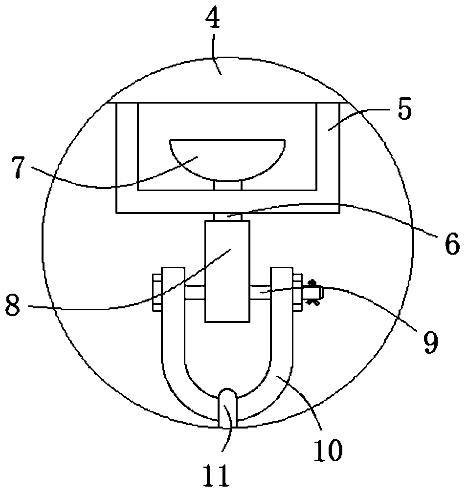
[0026] see figure 1 -6, a marine buoy, comprising a buoy 1, an instrument rack 2 is provided on the top surface of the buoy 1, a support frame 3 is provided on the bottom surface of the buoy 1, and a support plate 4 is provided on the side of the support frame 3, The bottom surface of the support plate 4 is provided with a channel steel 5, and the bottom surface of the channel steel 5 is provided with an adapter 6, and the top of the adapter 6 extends to the i...


PUM


Abstract

The invention relates to the technical field of ocean engineering equipment and discloses an ocean buoy which comprises a floating body, wherein an instrument rack is arranged on the top surface of the floating body; a support rack is arranged on the bottom surface of the floating body; a support plate is arranged on side surfaces of the support rack; channel steel is arranged on the bottom surface of the support plate; an adaptor is arranged on the bottom surface of the channel steel; the top end of the adaptor extends into the channel steel and is connected with a limiting part. Due to adoption of an arch-shaped anti-collision strip, the anti-collision strip is bent and deformed by stress preferably in the process that a ship is collided to the floating body, and cushioning stroke is increased; due to adoption of a variable cross section of the anti-collision strip, the stress to the floating body is slowly increased, the instantaneous impact force caused when the floating body collides to the ship is effectively reduced, the floating body is not deformed in the collision process, has a gravity center kept unchanged, is uniformly stressed when floating on the ocean surface, and is not overturned in sea waves, marine hydrology water quality meteorological data of ocean are normally collected after the ocean buoy is collided, and security of related operators and facilities canbe ensured.

Description

technical field [0001] The invention relates to the technical field of marine engineering equipment, in particular to a marine buoy. Background technique [0002] The ocean buoy is an automatic ocean observation station that can collect ocean hydrology, water quality and meteorological data around the clock, and send these data to the maritime department. Relevant personnel such as engineering and construction, so that relevant personnel can take necessary measures in advance to ensure the safety of personnel and facilities, and reduce losses caused by disasters such as strong winds and waves. The existing marine buoys are mainly composed of marine buoy systems and anchoring systems. Marine buoys The system includes a floating body 1, an instrument frame 2, a support frame 3, a rubber ring 15 and various instruments. The anchoring system includes an anchor chain 11, a shackle and a counterweight. The instrument frame 2 is installed on the top surface of the floating body 1, ...

Claims


Application Information

Patent Timeline
Patent Type & Authority Applications(China)
IPC IPC(8): B63B22/04B63B43/18
CPCB63B22/04B63B43/18B63B2022/006
Inventor 不公告发明人
Owner THE FIRST INST OF OCEANOGRAPHY SOA
Why Eureka
Try Eureka