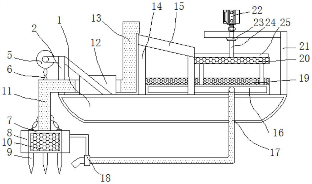
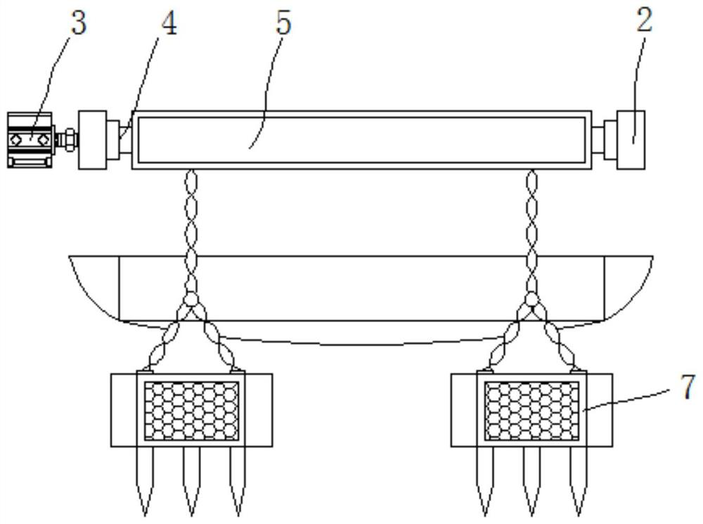
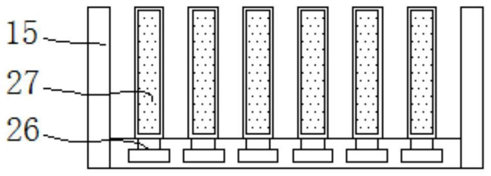
An anti-clogging sand pumping machine with multiple sets of sand pumping pipes

An anti-clogging, mechanical technology, used in mechanically driven excavators/dredgers, earth movers/shovels, construction, etc. Effect

Active Publication Date: 2021-07-06
杭州佳新智能系统有限公司
View PDF6 Cites 0 Cited by
  • Summary
  • Abstract
  • Description
  • Claims
  • Application Information

AI Technical Summary

Problems solved by technology

[0004] The object of the present invention is to provide an anti-blocking sand pumping machine with multiple sets of sand pumping pipes, to solve the problems in the above background technology. The existing Chinese invention patent application publication specification CN103758165 A discloses an energy-saving and environment-friendly pumping machine. Sand machine, although this energy-saving and environment-friendly sand pumping machine uses the turbulent flow generated by the potential energy difference between the inside and outside of the expansion tube to scour and loosen the sand at the bottom of the expansion tube, it does not need to be equipped with a reamer head to stir the sand at the bottom of the river. The damage of the cutter head affects the work, so the work efficiency is higher, but the power generated by the water level difference in the actual river is not enough to discharge the sand and water to the sand pumping boat. Even if the water flow is too fast, the efficiency of sand pumping is also very low.

Method used


Image

  • An anti-clogging sand pumping machine with multiple sets of sand pumping pipes
  • An anti-clogging sand pumping machine with multiple sets of sand pumping pipes
  • An anti-clogging sand pumping machine with multiple sets of sand pumping pipes

Examples


Embodiment Construction

[0028] The following will clearly and completely describe the technical solutions in the embodiments of the present invention with reference to the accompanying drawings in the embodiments of the present invention. Obviously, the described embodiments are only some, not all, embodiments of the present invention.

[0029] In the description of the present invention, unless otherwise stated, the meaning of "plurality" is two or more; the terms "upper", "lower", "left", "right", "inner", "outer" , "front end", "rear end", "head", "tail", etc. indicate the orientation or positional relationship based on the orientation or positional relationship shown in the drawings, and are only for the convenience of describing the present invention and simplifying the description, rather than Nothing indicating or implying that a referenced device or element must have a particular orientation, be constructed, and operate in a particular orientation should therefore not be construed as limiting ...


PUM


Abstract

The invention relates to an anti-clogging sand pumping machine with multiple sets of sand pumping pipes, comprising a hull and a water receiving box. The water tank and the hull are welded, the left side of the fixed frame is inlaid with a servo motor, and the side of the fixed frame close to the centerline of the hull is connected with a first rotating shaft, and the end of the first rotating shaft close to the centerline of the hull is installed There is a rotating drum, and a steel chain is installed at the lower end of the rotating drum, a sand pumping frame is fixed at the lower end of the steel chain, and weighting stones are arranged on both sides of the sand pumping frame. The beneficial effects of the present invention are: the weight of the sand pumping frame can be increased by the weighted stones on both sides, so that when the sand pumping frame descends at the horizontal position of the sand, it can automatically descend with the sand, so that the sand pumping frame can always be attached to the sand bed, then Make the sand inlet pipe keep the shortest distance with the sand all the time, and increase the sand suction degree of the sand inlet pipe.

Description

technical field [0001] The invention relates to the technical field of sand pumping machinery, in particular to an anti-blocking sand pumping machine with multiple sets of sand pumping pipes. Background technique [0002] Sand pumping machine is a kind of machine that pumps out the sand in the river. In recent years, with the rapid development of domestic real estate and other infrastructure industries, the demand for construction sand is also increasing. Most of the sand used for construction is river sand, which is generally collected by sand pumping machines to pump the sand and water from the bottom of the river to the sand pumping boat, and then pass through the screen to separate the sand and water. [0003] Disclosed in the Chinese Invention Patent Application Publication No. CN103758165 A is an energy-saving and environment-friendly sand pump. Although the energy-saving and environment-friendly sand pump utilizes the turbulent flow generated by the water level potent...

Claims


Application Information

Patent Timeline
Patent Type & Authority Patents(China)
IPC IPC(8): E02F5/28E02F3/88E02F3/90E02F3/92E02F7/04E02F7/06
CPCE02F3/885E02F3/90E02F3/902E02F3/92E02F3/9293E02F5/28E02F7/04E02F7/065
Inventor 付慧丽
Owner 杭州佳新智能系统有限公司
Why Eureka
Try Eureka