Fin enhanced heat exchange infrared suppressor and infrared suppression method

A technology of infrared suppression and enhanced heat transfer, which is applied to the cooling of machines/engines, jet propulsion devices, turbines/propulsion devices, etc. It can solve the problems of complex exhaust system structure and increased aircraft weight

Active Publication Date: 2019-04-12
NANJING UNIV OF AERONAUTICS & ASTRONAUTICS
View PDF9 Cites 8 Cited by
  • Summary
  • Abstract
  • Description
  • Claims
  • Application Information

AI Technical Summary

Problems solved by technology

[0009] There is still a lot of room for improvement in the infrared suppression capability of the existing infrared suppressor, and the existing infrared suppressor increases the weight of the aircraft and complicates the structure of the exhaust system

Method used


Image

  • Fin enhanced heat exchange infrared suppressor and infrared suppression method
  • Fin enhanced heat exchange infrared suppressor and infrared suppression method
  • Fin enhanced heat exchange infrared suppressor and infrared suppression method

Examples


Embodiment Construction

[0034] The present invention will be further explained below in conjunction with the accompanying drawings and embodiments.

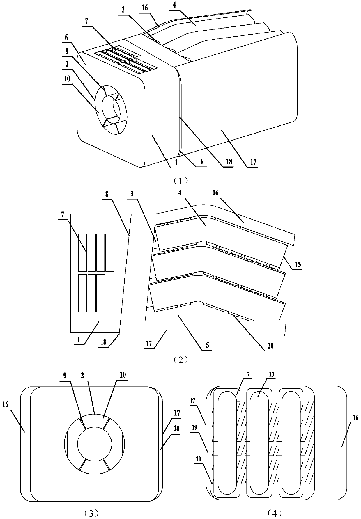
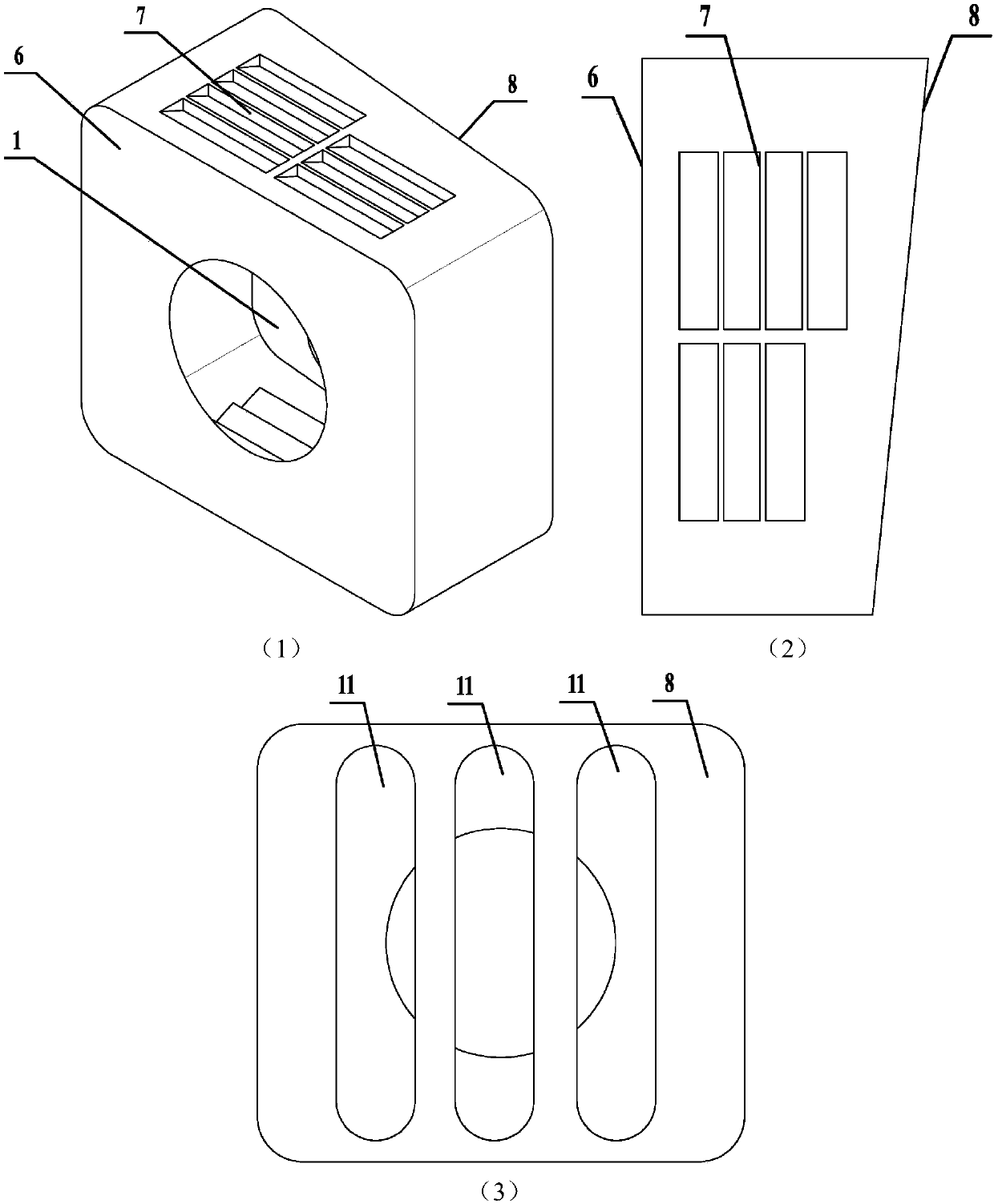
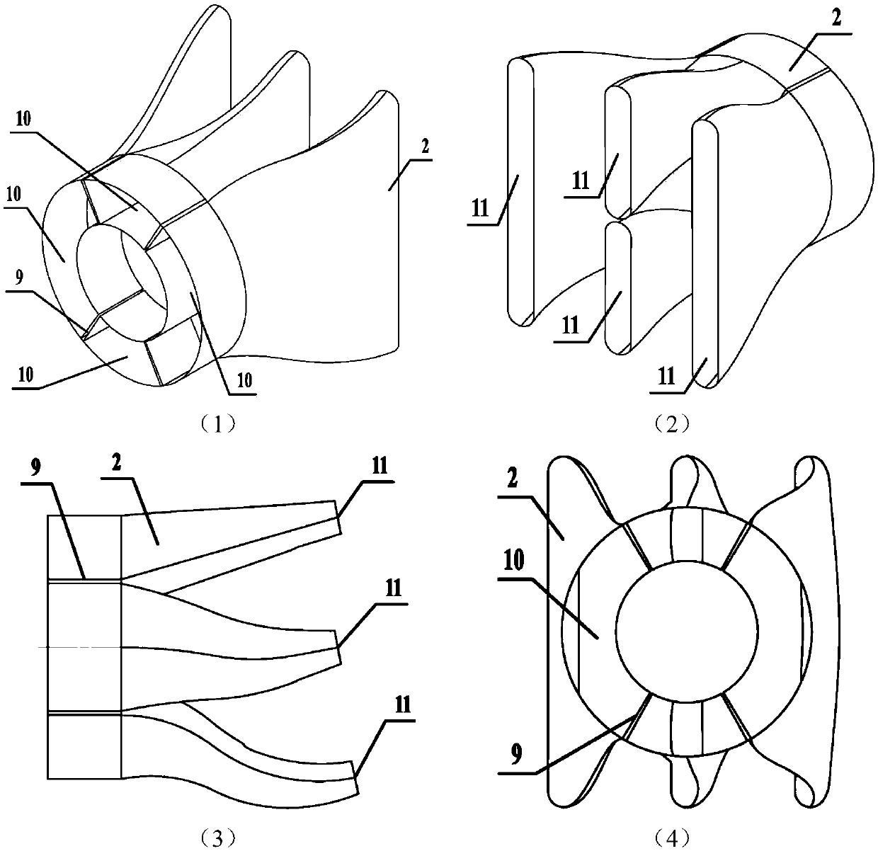
[0035] Please refer to Figure 1 to Figure 6 As shown, the fin-enhanced heat exchange multi-split infrared suppressor of the present invention includes a gas collection chamber 1, a multi-split nozzle 2, a mixing tube 3, a heat shield 4, and a heat exchange enhanced chamber 5.

[0036]The air-collecting chamber 3 is a cavity formed by a firewall 6, a baffle plate 8, and a side wall. The enhanced heat exchange cavity 5 is a cavity composed of skins on both sides and bottom. At the center of the plane where the firewall 6 is located, there are multiple air inlets 10 for the diverging nozzles, and the air inlets 10 for the multi-firing nozzles are annular. There are cold air inlets 7 on the upper and lower walls of the air collection chamber 1; the baffle plate 8 is the interface between the air collection chamber 1 and the enhanced heat exchange chamber...


PUM


Abstract

The invention discloses a fin enhanced heat exchange infrared suppressor which is suitable for an exhaust system of a turboshaft engine. The fin enhanced heat exchange infrared suppressor comprises anair collection chamber, a cold air inlet, a firewall, a plurality of shunting spray pipes, mixing pipes, heat insulation covers, fins and the like. On one hand, the momentum of the high-temperature gas behind the turbine is utilized to pump cold air in the air and then mix with the cold air to reduce the mainstream temperature in a core area; and on the other hand, the downwash airflow of a lifting rotor enters interlayers between the mixing pipes and the heat insulation covers, and the outer sides of the heat insulation covers, and the temperature at the surfaces of high-temperature components of the mixing pipes and the heat insulation covers is carried away through a fin enhanced heat exchange, so that the radiation heat transfer of the high-temperature components to the skin is reduced, and meanwhile, the mainstream temperature in the core area is reduced to a certain extent. In addition, a double-layer wall surface structure has good shielding and thermal insulation effects, anda sand-proof residual gas is introduced into a double-layer skin structure, so that the temperature of the machine body is basically consistent with the outside temperature and infrared radiation of the skin to the outside is further reduced.

Description

technical field [0001] The invention relates to an infrared suppressor for enhanced heat exchange with fins and an infrared suppression method, and belongs to the technical field of exhaust system design and infrared suppression of a helicopter turboshaft engine. Background technique [0002] (1) Research background of infrared suppressor: [0003] With the development of infrared detection and guidance technology, the continuous application of various detection and guidance technologies such as visible light, infrared, microwave and millimeter wave, the sensitivity of infrared detectors and the anti-jamming and target recognition capabilities of the system have been greatly improved. Survivability in high-tech battlefield environments will be increasingly threatened not only by ground-based anti-aircraft fires, but also by aerial fires. In a complex threat environment, infrared homing surface-to-air missiles, radar-guided anti-aircraft artillery and surface-to-air missiles...

Claims


Application Information

Patent Timeline
Patent Type & Authority Applications(China)
IPC IPC(8): F02K1/82F02K1/46F02C7/18
CPCF02C7/18F02K1/46F02K1/825
Inventor 单勇张伯安谭晓茗张靖周
Owner NANJING UNIV OF AERONAUTICS & ASTRONAUTICS
Why Eureka
Try Eureka